MCNP Sim of Jack Converter
Simulation inputs
Geometry


Materials legend for figures:

.
Assumptions
The beam spot size was given a diameter of 0.5 cm, which was determined by the size of a burn mark on a converter that got hot during irradiation. Electrons are 42 MeV and mono energetic.
.
Results
Neutrons
Energy spectrum
The plot below shows the energy distribution of neutrons exiting the converter at three different intervals of their angle w.r.t. the incident electron beam.
The neutron energy spectrum of the neutron-induced fission of U235 is also shown for comparison.

Misc
The difference between the U235 neutron spectrum and the energy spectrum from the converter may be partially due to moderation of neutrons by H2O. The plot below demonstrates this point, which registers the energy of each photo-neutron immediately after emission, as opposed to after the photo-neutrons exit the converter.
.png)
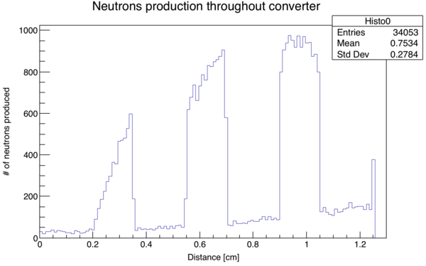
Below is a plot of the rate of neutron production as the beam traverses through the converter. Zero corresponds to where the beam enters the titanium window.

Photons
The plot below shows the energy distribution of photons exiting the converter at three different intervals of their angle w.r.t. the incident electron beam
