Go Back to All Lab Reports
Lab 6 Pulses and RC Filters
Differentiator
Construct the circuit below selecting an RC combination such that RC [math]\lt 10^{-4} [/math] s
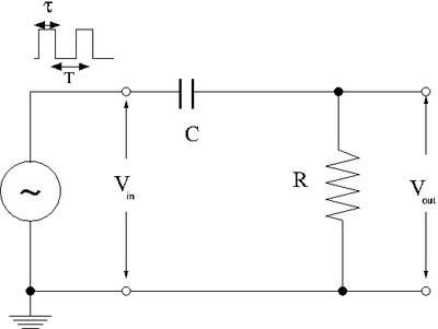
Taking [math]R = 989\ \Omega[/math] and [math]C_{out} = 1.255\ \mu F\ \Rightarrow \tau = RC = 1.24\ ms[/math]
Adjust the pulse generator to output square pulses which at [math]\tau \approx[/math] RC/10, RC and 10 RC
1) [math]\tau \approx \frac{1.24\ ms}{10} \approx 0.124\ ms [/math]

2) [math]\tau \approx 1.24\ ms [/math]

3) [math]\tau \approx 10 \cdot 12.4\ ms \approx 124\ ms [/math]
Measure[math] V_{in}[/math] and [math]V_{out}[/math]. Sketch a picture comparing[math] V_{out}[/math] and [math]V_{in}[/math]. ( 3*5 = 15 pnts.)
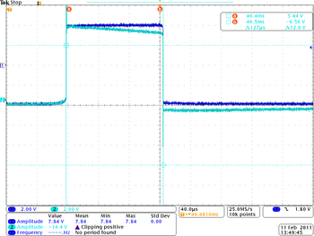
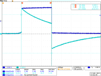
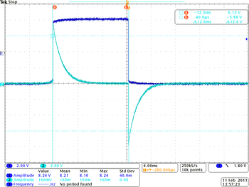
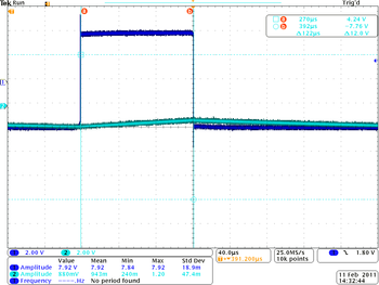
Table1. Differentiator circuit for different pulse width
| [math]\tau \approx 0.124\ ms [/math]
|
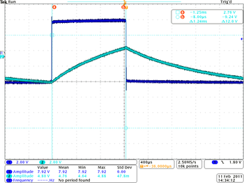
[math]\tau \approx 1.24\ ms [/math]
|
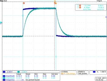
[math]\tau \approx 12.4\ ms [/math]
|
 |
 |
|
From the plots above (at point a):
[math]\tau = 0.124\ ms \rightarrow V_1 = 8.0\ V,\ V_2 = 8.0\ V[/math]
[math]\tau = 1.24\ ms \rightarrow V_1 = 8.0\ V,\ V_2 = 8.0\ V[/math]
[math]\tau = 12.4\ ms \rightarrow V_1 = 8.0\ V,\ V_2 = 8.0\ V[/math]
Questions
What happens if the amplitude of [math]V_{in}[/math] is doubled.( 5 pnts.)
The amplitude of [math]V_{out}[/math] is doubled as well.
What happens if R is doubled and C is halved?( 5 pnts.)
The times constant [math]\tau_{RC} = \frac{1}{(R/2)(2C)} = \frac{1}{RC}[/math] becomes unchangeable so nothing is really happened
Integrator
Now repeat the above experiment with the resistor and capacitor swapped to form the low pass circuit below.
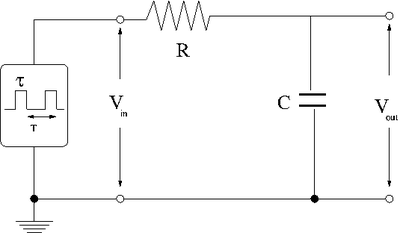
Table1. Integrating circuit for different pulse width
| [math]\tau \approx 0.124\ ms [/math]
|
[math]\tau \approx 1.24\ ms [/math]
|
[math]\tau \approx 12.4\ ms [/math]
|
 |
 |
|
From the plots above (at point b):
[math]\tau = 0.124\ ms \rightarrow V_1 = 8.0\ V,\ V_2 = 0.4\ V[/math]
[math]\tau = 1.24\ ms \rightarrow V_1 = 8.0\ V,\ V_2 = 4.4\ V[/math]
[math]\tau = 12.4\ ms \rightarrow V_1 = 8.0\ V,\ V_2 = 8.8\ V[/math]
Questions
What happens if the amplitude of [math]V_{in}[/math] is doubled.( 5 pnts.)
The amplitude of [math]V_{out}[/math] is doubled as well.
What happens if R is doubled and C is halved?( 5 pnts.)
The times constant [math]\tau_{RC} = \frac{1}{(R/2)(2C)} = \frac{1}{RC}[/math] becomes unchangeable so nothing is really happened
Pulse Sharpener
The goal of this section is to demonstrate how well the circuit below can sharpen an input pulse
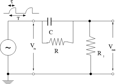
1.) The first step is to create an input pulse which is rounded, similar to the output of the integrator circuit when RC = 10 [math]\tau[/math]. You can do this using a capacitor shorted across the output of the pulse generator. This will essential be coupled to the input impedance of the pulse generator and form a low pass circuit.
As a result the input voltage is given as
- [math]V_{in} = V_0 \left ( 1 - e^{-t/\tau}\right )[/math]
where
- [math]\tau=R_{out} C_{out}[/math]
- [math]R_{out}[/math] = impedance of the function generator at output which produces V_{in}
- [math]C_{out}[/math] = capacitor shorting the function generator output to ground (not shown in the above picture)
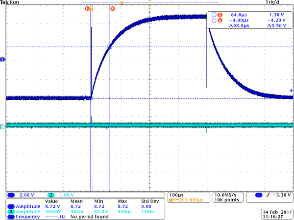
Taking [math]C_{out} = 1.235 \mu F[/math] and by measurement of rising time [math]\tau = RC = 68.0\ us[/math] I was able to estimate the input impedance of oscillator plus cable equal to [math]55\ \Omega[/math]. This measurements was done by taking oscillator input and plus capacitor shorted acros the output without any aditional circut.
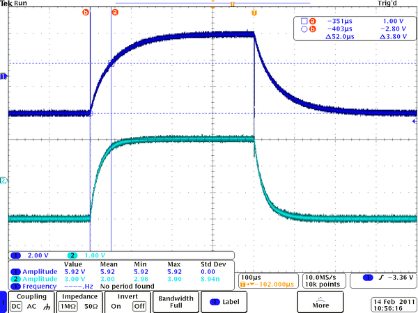
2.) The output should be given by
- [math]V_{out} = V_0^{\prime} \left ( 1 - e^{-t/\tau^{\prime}}\right )[/math]
where
- [math]\tau^{\prime} =\left ( \frac{R_1 R}{R_1+ R}\right )C_1[/math]
Taking [math]R = 49.9\ \Omega ,[/math] [math]R_1 = 51.2\ \Omega[/math] and [math]C_1 = 1.225\ \mu F\ \Rightarrow \tau^{\prime} = \left ( \frac{R_1 R}{R_1+ R}\right )C_1 = 31.0\ us[/math]
Make measurements of the rise time [math]\tau[/math] and [math]\tau^{\prime}[/math]. The rise time is defined as the time it take the pulse to go from 10% of its max value to 90% of its max value.( 5 pnts.)
Rise time [math]\tau[/math] measurements
- Input voltage is given by [math]V_{in} = V_0 \left ( 1 - e^{-t/\tau}\right ),\ V_0 = 6\ V[/math]
- At time [math]t = 0 \rightarrow V_{in} = 0[/math]
- At time [math]t = \tau \rightarrow V_{in} = 6 \left ( 1 - e^{-1}\right ) = 3.79\ V[/math]
- From the plot above my measurement of rise time is:
[math]\tau = (52 \pm 0.2)\ us[/math]
Rise time [math]\tau^{\prime}[/math] measurements
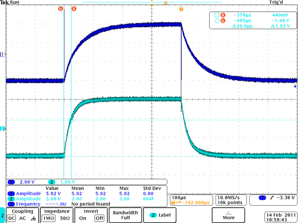
- Output voltage is given by [math]V_{out} = V_0^{\prime} \left ( 1 - e^{-t/\tau^{\prime}}\right ),\ V_0^{\prime} = 3.04\ V[/math]
- At time [math]t = 0 \rightarrow V_0^{\prime} = 0[/math]
- At time [math]t = \tau^{\prime} \rightarrow V_0^{\prime} = 3.04 \left ( 1 - e^{-1}\right ) = 1.92\ V[/math]
- From the plot above my measurement of rise time is:
[math]\tau^{\prime} = (26.0 \pm 2.0)\ us[/math]
Compare the measurement of [math]\tau^{\prime}[/math] to what you expected based on your measured values of [math]C_1[/math], [math]R_1[/math] and [math]R[/math].( 15 pnts.)
Expected value:
Taking
- [math]R = (49.8 \pm 0.1)\ \Omega ,[/math] [math]R_1 = (51.1\ \pm 0.1)\ \Omega[/math] and [math]C_1 = (1.225\ \pm 0.05)\ \mu F[/math]
I was able to estimate the expected value of rising time is equal to
- [math] \tau^{\prime} = \left ( \frac{R_1 R}{R_1+ R}\right )C_1 = (30.9\ \pm 0.13)\ us[/math]
Measured value:
Our measured value of rising time is equal to
- [math]\tau^{\prime} = (26.0 \pm 2.0)\ us[/math]
As we can see from results above my measured and expected value different one from each other more then absolute values of error interval. The reason can be in derivation of expected value of [math] \tau^{\prime} = \left ( \frac{R_1 R}{R_1+ R}\right )C_1[/math]. This result is the solution of inhomogeneous differential equation:
[math]\frac{dV_{out}}{dt} + \frac{(R+R_1)}{CRR_1} V_{out} = V_0 \left ( \frac{1}{\tau_{in}} - \frac{1}{CR}\right )e^{-t/\tau_{in}} + \frac{V_0}{CR} [/math]
And in order to this result be true the [math]\tau_{in}[/math] should be equal to [math]R\ C[/math]. Then the term [math]\left ( \frac{1}{\tau_{in}} - \frac{1}{CR}\right )[/math] in equation above will be zero and the solution becomes [math]V_{out} = \frac{R\ R_1}{R+R_1}V_0 (1- e^{-t/\tau_{out}})[/math]
where [math]\tau_{out} = C \frac{RR_1}{R+R_1} [/math] that gives us the result above about rising time of output voltage.
In real situation the term [math]\left ( \frac{1}{\tau_{in}} - \frac{1}{CR}\right )[/math] is not equal to zero and we can not really use the formula [math] \tau^{\prime} = \left ( \frac{R_1 R}{R_1+ R}\right )C_1[/math]. In this case the theoretical values of expected error is difficult to handle. We need somehow to solve this equation exactly that could be done numerically or we need somehow to estimate the error of not including this term in equation.
Questions
1.) Qualitatify, why is [math]\tau^{\prime} \lt \tau[/math]?( 10 pnts.)
2.) How is [math]V_{out}[/math] worse than [math]V_{in}[/math]( 10 pnts.)
Forest_Electronic_Instrumentation_and_Measurement
Go Back to All Lab Reports


