Go Back to All Lab Reports
- LC Resonance circuits
The LC circuit
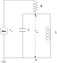
Design a parallel LC resonant circuit with a resonant frequency between 50-200 kHz. use [math]L[/math] = 10 - 100 [math]\mu H[/math], R = 1k [math]\Omega[/math]
- [math]\omega_0=\frac{1}{\sqrt{\mbox{LC}}}[/math]
I choose the following values for [math]\mbox{L}[/math] and [math]\mbox{C}[/math]:
- [math]\mbox{L}=33\ \mu H[/math]
- [math]\mbox{C}=1.024\ \mu F[/math]
- [math]\mbox{R}=0.989\ k \Omega[/math]
- [math]\mbox{R}_L=2.5\ \Omega[/math]
So the resonance frequency is [math]\omega_0=\frac{1}{\sqrt{33\ \mu H \cdot 1.024\ \mu F}} = 172 \cdot 10^3\ \frac{\mbox{rad}}{\mbox{sec}}[/math]
- [math]f=\frac{\omega_0}{2\pi} = 27.4\ \mbox{kHz}[/math]
And
- [math]\mbox{Q} = \frac{1}{\mbox{R}} \sqrt{\frac{\mbox{L}}{\mbox{C}}} = 2.27[/math]
Construct the LC circuit using a non-polar capacitor
Measure the Gain [math]\equiv \frac{V_{out}}{V_{in}}[/math] as a function of frequency. (25 pnts)
Compare the measured and theoretical values of the resonance frequency ([math]\omega_{L}[/math]) (10 pnts)
Questions
1.Is there a value of [math]R[/math] in which [math]V_{out} \approx V_{in}[/math] at resonance. What is the value?(5 pnts)
The RLC cicuit
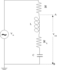
Design and construct a series LRC circuit
Measure and Graph the Gain as a function of the oscillating input voltage frequency. (25 pnts)
Measure and Graph the Phase Shift as a function of the oscillating input voltage frequency. (25 pnts)
Questions
What is the current [math]I[/math] at resonance? (5 pnts)
What is the current as [math]\nu \rightarrow \infty[/math]? (5 pnts)
Forest_Electronic_Instrumentation_and_Measurement
Go Back to All Lab Reports

