Difference between revisions of "Lab 3 TF EIM"
Jump to navigation
Jump to search
| Line 41: | Line 41: | ||
#compare the theoretical and experimentally measured break frequencies. (5 pnts) | #compare the theoretical and experimentally measured break frequencies. (5 pnts) | ||
#Calculate and expression for <math>\frac{V_{out}}{ V_{in}}</math> as a function of <math>\nu</math>, <math>R</math>, and <math>C</math>. The Gain is defined as the ratio of <math>V_{out}</math> to <math>V_{in}</math>.(5 pnts) | #Calculate and expression for <math>\frac{V_{out}}{ V_{in}}</math> as a function of <math>\nu</math>, <math>R</math>, and <math>C</math>. The Gain is defined as the ratio of <math>V_{out}</math> to <math>V_{in}</math>.(5 pnts) | ||
| + | #Sketch the phasor diagram for <math>V_{in}</math>,<math> V_{out}</math>, <math>V_{R}</math>, and <math>V_{C}</math>. Put the current <math>i</math> along the real voltage axis. (30 pnts) | ||
#Compare the theoretical and experimental value for the phase shift <math>\theta</math>. (5 pnts) | #Compare the theoretical and experimental value for the phase shift <math>\theta</math>. (5 pnts) | ||
| − | |||
# what is the phase shift <math>\theta</math> for a DC input and a very-high frequency input?(5 pnts) | # what is the phase shift <math>\theta</math> for a DC input and a very-high frequency input?(5 pnts) | ||
# calculate and expression for the phase shift <math>\theta</math> as a function of <math>\nu</math>, <math>R</math>, <math>C</math> and graph <math>\theta</math> -vs <math>\nu</math>. (20 pnts) | # calculate and expression for the phase shift <math>\theta</math> as a function of <math>\nu</math>, <math>R</math>, <math>C</math> and graph <math>\theta</math> -vs <math>\nu</math>. (20 pnts) | ||
Revision as of 06:11, 21 January 2011
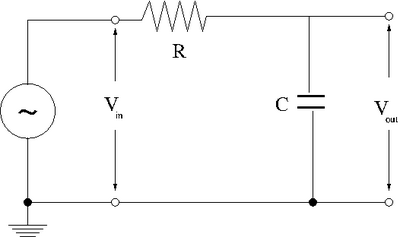
- RC Low-pass filter
1-50 kHz filter (20 pnts)
- Design a low-pass RC filter with a break point between 1-50 kHz. The break point is the frequency at which the filter starts to attenuate the AC signal. For a Low pass filter, AC signals with a frequency above 1-50 kHz will start to be attenuated (not passed).
- Now construct the circuit using a non-polar capacitor.
- use a sinusoidal variable frequency oscillator to provide an input voltage to your filter.
- Measure the input and output voltages for at least 8 different frequencies which span the frequency range from 1 Hz to 1 MHz.

| Hz | Volts | Volts | |
- Graph the -vs-
phase shift (10 pnts)
- measure the phase shift between and
Questions
- compare the theoretical and experimentally measured break frequencies. (5 pnts)
- Calculate and expression for as a function of , , and . The Gain is defined as the ratio of to .(5 pnts)
- Sketch the phasor diagram for ,, , and . Put the current along the real voltage axis. (30 pnts)
- Compare the theoretical and experimental value for the phase shift . (5 pnts)
- what is the phase shift for a DC input and a very-high frequency input?(5 pnts)
- calculate and expression for the phase shift as a function of , , and graph -vs . (20 pnts)