Lab 23 TF EIM
Jump to navigation
Jump to search
Inverting OP Amp
1. Construct the inverting amplifier according to the wiring diagram below.

2. insert a 0.1 F capacitor between ground and the OP power supply input pin.
Gain measurements
- Measure the gain as a function of frequency between 100 Hz and 2 MHz for three values of R_2 = 10 k, 100 k, 1M.
- Graph the above measurements with the Gain in units of decibels (dB) and with a logarithmic scale for the frequency axis.
Impedance
Input Impedance
- Measure for the 10 fold and 100 fold amplifier at ~100 Hz and 10 kHz frequency.
Output Impedance
- Measure for the 10 fold and 100 fold amplifier at ~100 Hz and 10 kHz frequency. Be sure to keep the output () undistorted
and
Use the above equation and two measurements of , , and to extract and .
- measure for = 1 k, = 100 k, and=0 (grounded).
- measure for = 10 k, = 1 M, and=0 (grounded).
- You can now construct 2 equations with 2 unknowns and .
Now we will put in a pull up resistor R_3 as shown below.

Instead of the current we have the current
Use the same technique and resistors from the previous section to construct 2 equations and 2 unknowns and extract , keep =0.
The offset Null Circuit
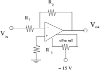

- Construct the offset null circuit below.
- Adjust the potentiometer to minimize with .
- Use a scope to measure the output noise.
Capacitors
- Revert back to the pull up resistor
Capacitor in parallel with
- Select a capacitor such that when = 10 kHz.
- Add the capacitor in parallel to so you have the circuit shown below.

- Use a pulse generator to input a sinusoidal voltage
- Measure the Gain as a function of the frequency and plot it.
Capacitor in series with R_1
- Select a capacitor such that when = 1 kHz.
- Add the capacitor in series to so you have the circuit shown below.

- Use a pulse generator to input a sinusoidal voltage
- Measure the Gain as a function of the frequency and plot it.
Slew rate
Measure the slew and compare it to the factory spec.
Power Supply Rejection Ratio
- Set V_{in} = 0.
- Measure while changing