|
|
| Line 76: |
Line 76: |
| | | | |
| | I used | | I used |
| − | <math>R_1 = (197.7 \pm 0.5)\ k\Omega <math> | + | <math>R_1 = (197.7 \pm 0.5)\ k\Omega </math> |
| − | <math>R_1 = (197.5 \pm 0.5)\ k\Omega <math> | + | <math>R_1 = (197.5 \pm 0.5)\ k\Omega </math> |
| − | <math>R_1 = (99.5 \pm 0.5)\ k\Omega <math> | + | <math>R_1 = (99.5 \pm 0.5)\ k\Omega </math> |
| − | <math>R_B = (R_1 + R_2 + R_3) = (494.7 \pm 3.1)\ k\Omega <math> | + | <math>R_B = (R_1 + R_2 + R_3) = (494.7 \pm 3.1)\ k\Omega </math> |
| | and | | and |
| − | <math>R_E = (100.0 \pm 0.5)\ Omega <math> | + | <math>R_E = (100.0 \pm 0.5)\ Omega </math> |
| | | | |
| | | | |
Revision as of 06:35, 11 March 2011
Go Back to All Lab Reports
DC Bipolar Transistor Curves
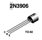
Data sheet for transistors.
Media:2N3904.pdfMedia:2N3906.pdf
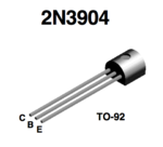
Using 2N3904 is more srtaight forward in this lab.
Transistor circuit
Identify the type (n-p-n or p-n-p) of transistor you are using and fill in the following specifications.
I am going to use n-p-n transistor 2N3904. Below are some specifications from data shits for this type of transistor:
| Value
|
Description
|
| [math]V_{(BR)CEO} = 40\ V[/math] |
Collector-Base breakdown voltage
|
| [math]V_{(BR)EBO} = 6\ V[/math] |
Emitter-Base Breakdown Voltage
|
| [math]V_{(BR)CEO} = 40\ V[/math] |
Maximum Collector-Emitter Voltage
|
| [math]V_{(BR)CBO} = 60\ V[/math] |
Maximum Collector-Emitter Voltage
|
| [math]I_C = 200\ mA[/math] |
Maximum Collector Current - Continuous
|
| [math]P = 625\ mW[/math] |
Transistor Power rating([math]P_{Max}[/math])
|
| [math]h_{FE}\ min \ [/math] |
[math]h_{FE}\ max \ [/math] |
[math]I_C[/math], [math]V_{CE}[/math]
|
| 40 |
300 |
[math]I_C=0.1\ mA[/math], [math]V_{CE}=1.0\ V[/math]
|
| 70 |
300 |
[math]I_C=1\ mA[/math], [math]V_{CE}=1.0\ V[/math]
|
| 100 |
300 |
[math]I_C=10\ mA[/math], [math]V_{CE}=1.0\ V[/math]
|
| 60 |
300 |
[math]I_C=50\ mA[/math], [math]V_{CE}=1.0\ V[/math]
|
| 30 |
300 |
[math]I_C=100\ mA[/math], [math]V_{CE}=1.0\ V[/math]
|
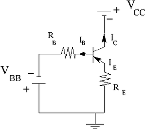
Construct the circuit below according to the type of transistor you have.
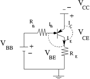
Let [math]R_E = 100 \Omega[/math].
[math]V_{CC} \lt 5 Volts[/math] variable power supply
[math]V_{BE}= 1\ V[/math].
Find the resistors you need to have
[math]I_B = 2 \mu A[/math] , [math]5 \mu A[/math] , and [math]10 \mu A[/math]
By measurements I was able to find that [math]V_{BE}= 0.6\ V[/math]. So I am going to use this value. Also let picks up [math]V_{BB}= 1.6\ V[/math]. So my current [math]I_B = \frac{V_{BB} - V_{BE}}{R_B} = \frac{(1.6 - 0.6)\ V}{R_B} = \frac{1.0\ V}{R_B}[/math].
Now to get [math]I_B = 2\ \mu A[/math] I need to use [math]R_B = \frac{1.0\ V}{2\ \mu A} = 500\ k\Omega[/math]
    To get [math]I_B = 5\ \mu A[/math] I need to use [math]R_B = \frac{1.0\ V}{5\ \mu A} = 200\ k\Omega[/math]
    To get [math]I_B = 10\ \mu A[/math] I need to use [math]R_B = \frac{1.0\ V}{10\ \mu A} = 100\ k\Omega[/math]
Measure the emitter current [math]I_E[/math] for several values of [math]V_{CE}[/math] by changing [math]V_{CC}[/math] such that the base current [math]I_B = 2 \mu[/math] A is constant. [math]I_B \approx \frac{V_{BB}-V_{BE}}{R_B}[/math]
I used
[math]R_1 = (197.7 \pm 0.5)\ k\Omega [/math]
[math]R_1 = (197.5 \pm 0.5)\ k\Omega [/math]
[math]R_1 = (99.5 \pm 0.5)\ k\Omega [/math]
[math]R_B = (R_1 + R_2 + R_3) = (494.7 \pm 3.1)\ k\Omega [/math]
and
[math]R_E = (100.0 \pm 0.5)\ Omega [/math]
| [math]V_{CC}[/math]
|
[math]V_{B}[/math]
|
[math]V_{BB}[/math]
|
[math]V_{EC}[/math]
|
[math]V_{E}[/math]
|
[math]R_{E}[/math]
|
[math]R_{B}[/math]
|
[math]I_{E} = \frac{V_E}{R_E}[/math]
|
[math]I_{B} = \frac{V_{BB}-V_B}{R_B}[/math]
|
[math]P_{max} = I_{C}\cdot V_{EC} [/math]
|
| mV |
mV |
V |
mV |
mV |
[math]\Omega[/math] |
k[math]\Omega[/math] |
mA |
[math]\mu A[/math] |
[math]\mu W[/math]
|
| [math]41.5\pm 0.5[/math] |
[math]600\pm 50[/math] |
[math]1.6\pm 0.05[/math] |
[math]0.0\pm 1[/math] |
[math]40\pm 2[/math] |
[math]100\pm 0.5[/math] |
[math]494.7\pm 3.1[/math] |
0.40±0.02 |
2.02±0.18 |
0.00±0.40
|
| [math]106.7\pm 0.5[/math] |
[math]600\pm 50[/math] |
[math]1.6\pm 0.05[/math] |
[math]4.0\pm 1[/math] |
[math]100\pm 5[/math] |
[math]100\pm 0.5[/math] |
[math]494.7\pm 3.1[/math] |
1.00±0.05 |
2.02±0.18 |
4.00±1.02
|
| [math]142.0\pm 0.5[/math] |
[math]600\pm 50[/math] |
[math]1.6\pm 0.05[/math] |
[math]10.0\pm 1[/math] |
[math]140\pm 5[/math] |
[math]100\pm 0.5[/math] |
[math]494.7\pm 3.1[/math] |
1.40±0.05 |
2.02±0.18 |
14.00±1.49
|
| [math]170.8\pm 0.5[/math] |
[math]600\pm 50[/math] |
[math]1.6\pm 0.05[/math] |
[math]16.0\pm 1[/math] |
[math]170\pm 5[/math] |
[math]100\pm 0.5[/math] |
[math]494.7\pm 3.1[/math] |
1.70±0.05 |
2.02±0.18 |
27.20±1.88
|
| [math]204.9\pm 0.5[/math] |
[math]600\pm 50[/math] |
[math]1.6\pm 0.05[/math] |
[math]22.0\pm 1[/math] |
[math]200\pm 5[/math] |
[math]100\pm 0.5[/math] |
[math]494.7\pm 3.1[/math] |
2.00±0.05 |
2.02±0.18 |
44.00±2.29
|
| [math]233.0\pm 0.5[/math] |
[math]600\pm 50[/math] |
[math]1.6\pm 0.05[/math] |
[math]26.0\pm 1[/math] |
[math]240\pm 10[/math] |
[math]100\pm 0.5[/math] |
[math]494.7\pm 3.1[/math] |
2.4±0.10 |
2.02±0.18 |
62.40±3.55
|
| [math]266.2\pm 0.5[/math] |
[math]600\pm 50[/math] |
[math]1.6\pm 0.05[/math] |
[math]28.0\pm 1[/math] |
[math]260\pm 10[/math] |
[math]100\pm 0.5[/math] |
[math]494.7\pm 3.1[/math] |
2.60±0.10 |
2.02±0.18 |
72.80±3.84
|
| [math]296.1\pm 0.5[/math] |
[math]600\pm 50[/math] |
[math]1.6\pm 0.05[/math] |
[math]29.0\pm 1[/math] |
[math]300\pm 10[/math] |
[math]100\pm 0.5[/math] |
[math]494.7\pm 3.1[/math] |
3.00±0.10 |
2.02±0.18 |
87.00±4.20
|
| [math]338.0\pm 0.5[/math] |
[math]600\pm 50[/math] |
[math]1.6\pm 0.05[/math] |
[math]29.0\pm 1[/math] |
[math]340\pm 10[/math] |
[math]100\pm 0.5[/math] |
[math]494.7\pm 3.1[/math] |
3.40±0.10 |
2.02±0.18 |
98.60±4.50
|
| [math]406.0\pm 2.0[/math] |
[math]600\pm 50[/math] |
[math]1.6\pm 0.05[/math] |
[math]29.0\pm 1[/math] |
[math]400\pm 10[/math] |
[math]100\pm 0.5[/math] |
[math]494.7\pm 3.1[/math] |
4.00±0.10 |
2.02±0.18 |
116.00±4.97
|
| [math]554.0\pm 2.0[/math] |
[math]600\pm 50[/math] |
[math]1.6\pm 0.05[/math] |
[math]29.0\pm 1[/math] |
[math]560\pm 20[/math] |
[math]100\pm 0.5[/math] |
[math]494.7\pm 3.1[/math] |
5.60±0.20 |
2.02±0.18 |
162.40±8.10
|
| [math]809.0\pm 2.0[/math] |
[math]600\pm 50[/math] |
[math]1.6\pm 0.05[/math] |
[math]30.0\pm 1[/math] |
[math]800\pm 20[/math] |
[math]100\pm 0.5[/math] |
[math]494.7\pm 3.1[/math] |
8.00±0.20 |
2.02±0.18 |
240.00±10.07
|
| [math]1041.0\pm 2.0[/math] |
[math]600\pm 50[/math] |
[math]1.6\pm 0.05[/math] |
[math]30.0\pm 1[/math] |
[math]1000\pm 50[/math] |
[math]100\pm 0.5[/math] |
[math]494.7\pm 3.1[/math] |
10.00±0.50 |
2.02±0.18 |
300.00±18.09
|
Repeat the previous measurements for [math]I_B \approx 5 \mbox{ and } 10 \mu[/math] A. Remember to keep [math]I_CV_{CE} \lt P_{max}[/math] so the transistor doesn't burn out
| V_{CC} |
V_B |
V_{BB} |
V_ {EC} |
V_ E |
R_E |
R_B |
I_E |
I_B
|
| mV |
mV |
V |
mV |
mV |
[math]\Omega[/math] |
k[math]\Omega[/math] |
mA |
\muA
|
|
|
|
|
|
|
|
|
|
5.) Graph [math]I_C[/math] -vs- [math]V_{CE}[/math] for each value of [math]I_B[/math] and [math]V_{CC}[/math] above. (40 pnts)
6.) Overlay points from the transistor's data sheet on the graph in part 5.).(10 pnts)
Questions
- Compare your measured value of [math]h_{FE}[/math] or [math]\beta[/math] for the transistor to the spec sheet? (10 pnts)
- What is [math]\alpha[/math] for the transistor?(10 pnts)
- The base must always be more _________(________) than the emitter for a npn (pnp)transistor to conduct I_C.(10 pnts)
- For a transistor to conduct I_C the base-emitter junction must be ___________ biased.(10 pnts)
- For a transistor to conduct I_C the collector-base junction must be ___________ biased.(10 pnts)
Measure the Base-Emmiter breakdown voltage. (10 pnts)
I expect to see a graph [math](I_{B} -vs- V_{BE} )[/math] and a linear fit which is similar to the forward biased diode curves. Compare your result to what is reported in the data sheet.
Go Back to All Lab Reports Forest_Electronic_Instrumentation_and_Measurement


