Difference between revisions of "Lab 10 TF EIM"
Jump to navigation
Jump to search
| Line 29: | Line 29: | ||
[[File:TF_EIM_Lab10_HW_RectifierBridge.png| 400 px]] | [[File:TF_EIM_Lab10_HW_RectifierBridge.png| 400 px]] | ||
| + | |||
| + | |||
| + | 1.) Choose R in the above circuit so the low-pass filter breakpoint is less than 60 Hz. | ||
| + | |||
| + | 2.) Measure the quantities below using at least 4 different load resistors. | ||
| + | |||
[[Forest_Electronic_Instrumentation_and_Measurement]] | [[Forest_Electronic_Instrumentation_and_Measurement]] | ||
Revision as of 18:05, 2 March 2011
Unregulated power supply
Use a transformer for the experiment.
here is a description of the transformer.
File:TF EIM 241 transformer.pdf
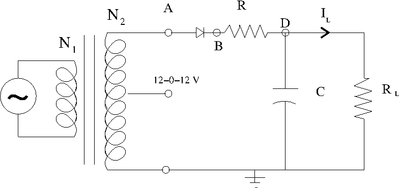
Half-Wave Rectifier Circuit
1.)Consider building circuit below.
Determine the components needed in order to make the output ripple have a less than 1 Volt.
List the components below and show your instructor the output observed on the scope.
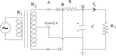
Full-Wave Rectifier Circuit
Determine the components needed in order to make the above circuit's output ripple have a less than 0.5 Volt.
List the components below and show your instructor the output observed on the scope.
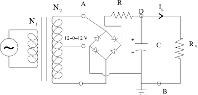
Full-Wave Rectifier Bridge Circuit
1.) Choose R in the above circuit so the low-pass filter breakpoint is less than 60 Hz.
2.) Measure the quantities below using at least 4 different load resistors.


