Difference between revisions of "KiwiDipole"
Jump to navigation
Jump to search
m (Added some pictures. -gist) |
|||
| Line 1: | Line 1: | ||
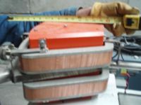
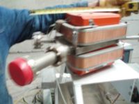
| − | The picture below show the dipoles we would like to use for the positron beam line | + | The picture below show the dipoles we would like to use for the positron beam line: |
| + | |||
[[Image:KiwiDipole_D3_Side1.jpg | 200 px]] | [[Image:KiwiDipole_D3_Side1.jpg | 200 px]] | ||
[[Image:KiwiDipole_D3_Side2.jpg| 200 px]] | [[Image:KiwiDipole_D3_Side2.jpg| 200 px]] | ||
| Line 9: | Line 10: | ||
[[Image:KiwiDipole_downstream.jpg | 200 px]] | [[Image:KiwiDipole_downstream.jpg | 200 px]] | ||
| − | We need to build a | + | We need to build a vacuum chamber to fit in between the 1" pole gap which will have flanges with which to attach the beam line. The chambers shown in the above pictures have the dimensions shown below. |
[[Image:KiwiDipol_BrettsVacumChamber.jpg | 200 px]] | [[Image:KiwiDipol_BrettsVacumChamber.jpg | 200 px]] | ||
Latest revision as of 16:02, 26 May 2009
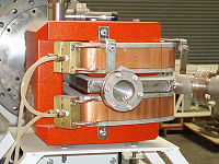
The picture below show the dipoles we would like to use for the positron beam line:
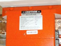
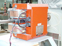
More pictures:
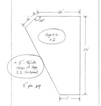
We need to build a vacuum chamber to fit in between the 1" pole gap which will have flanges with which to attach the beam line. The chambers shown in the above pictures have the dimensions shown below.
Autocad Technical drawings for the Dipole are given below in "dwg" format.
Media:KiwiDipole_AutoCadDWG1.txt
Media:KiwiDipole_AutoCadDWG2.dwg.txt
Media:KiwiDipole_AutoCadDWG3.dwg.txt
Media:KiwiDipole_AutoCadDWG4.dwg.txt
Media:KiwiDipole_AutoCadDWG5.dwg.txt
