Difference between revisions of "June, 7, 2007 Cf rate measurements using Photonics PMT"
| (38 intermediate revisions by the same user not shown) | |||
| Line 40: | Line 40: | ||
It was simulated the test of equipment described above. | It was simulated the test of equipment described above. | ||
| − | Cf-252 neutron source was presented as spherical source (2 cm in diameter) which emitts neutrons from the surface in 4pi. Also material of plastic scintillator was simulated and response function was obtained. | + | Cf-252 neutron source was presented as spherical source (2 cm in diameter) which emitts neutrons from the surface in 4pi. Also material of plastic scintillator was simulated and response function was obtained. The total number of neutrons emitted by source (670000 n) was fitted to experimental data. In this case experimental counting rate (w/o any attenuator) was 2700 cpm. Simulated counting rate was 2581 "cpm". It was supposed that Cf-252 emitts neutrons only. So, if we find the difference in counting rates wrt attenuator materials, we will be able to say what is percentage of gamma-rays our Cf source emitts. Spectrum of netrons simulated can be found blow. |
| + | |||
| + | [[Image:Energy_deposited_in_BC-420.jpg]] | ||
| + | |||
| + | [[Image:Energy_deposited_in_BC-420_steel.jpg]] | ||
| + | |||
| + | [[Image:Energy_deposited_in_BC-420_lead.jpg]] | ||
| + | |||
| + | [[Image:6_3cm_paraffin.jpg]] | ||
| + | |||
| + | [[Image:2x6_3cm_paraffin.jpg]] | ||
| + | |||
| + | |||
| + | (i) layer of steel (2.5 cm) passes 92% of the incident neutron flux (81% of total flux in experiment - 72.9% n & 8.1% <math>\gamma</math> (or whatever)) | ||
| + | |||
| + | (ii) layer of lead (5 cm) passes 89.2% of the incident neutron flux (30% of total flux in experiment - 26.76% n & 3.24% <math>\gamma</math>) | ||
| + | |||
| + | (iii) layer of paraffin wax (6.3 cm) passes 44.2% of the incident neutron flux (81% of total flux in experiment - 35.8% n & 45.2% <math>\gamma</math>) | ||
| + | |||
| + | (iv) layer of paraffin wax (2x6.3 cm) passes 32% of the incident neutron flux (2.6% of total flux in experiment - 0.83% n & 1.77% <math>\gamma</math>) | ||
| + | |||
| + | [[Image:lead_gamma_spectrum.jpg]] | ||
= Analysis = | = Analysis = | ||
Latest revision as of 18:49, 29 June 2007
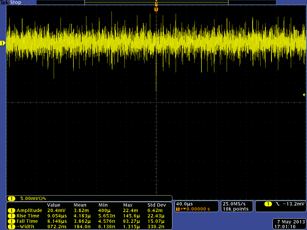
The 60 Ci Cf-252 source was placed 16.5 cm away from the face of the BC420 scintilator which is attached to the Photonics PMT whose base was set to -1200 Volts. The PMT output signal was descriminated by a Lecroy Model 821 descriminator set to pass any voltage below -0.5 mV. The descriminated output was then sent to a counter Model TC 531.
Configuration Definitions
1: Placed the Cf source 16.5 cm from face of Scintillator. neutrons passing through scintillator would also pass through PMT
2: Inserted a 2.5 cm thick steel shielding wall between Scintillator and Cf source. Right up against Scintillator
3: Replaced steel wall with 5 cm thick lead shielding brick
4: Replaced lead brick with 6.7 cm thick paraffin block ( Paraffin N.F. , Household wax made by Parowax. 4 cackes, total net weight 16 oz (454 g))
5: Increased thickness of paraffin block to 13.4 cm
6: No source backround
Measurements
Using Photonics PMT and BC420 plastic scintillator
| Configuration | Rate (counts/min) | Statistical Error in Rate (Counts/min) |
|---|---|---|
| 1 | 2.7e3 | 0.09e3 |
| 2 | 2.2e3 | 0.01e3 |
| 3 | 0.8e3 | 0.02e3 |
| 4 | 2.2e3 | 0.08e3 |
| 5 | 1.8e3 | 0.02e3 |
| 6 | 0.07e3 | 0.005e3 |
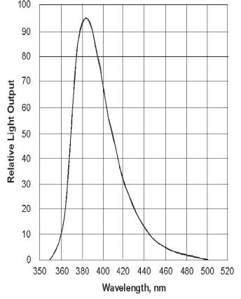
BC-420 response function (http://www.detectors.saint-gobain.com/media/documents/S0000000000000001004/SGC_BC418,420,422DataSheet1005.pdf):
It was simulated the test of equipment described above.
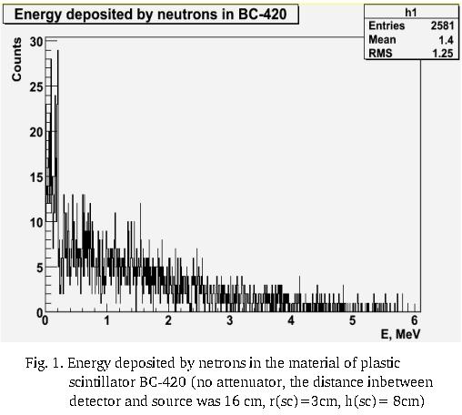
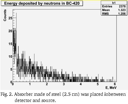
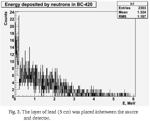
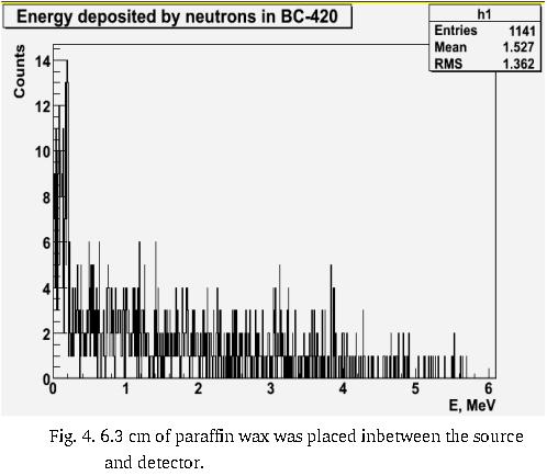
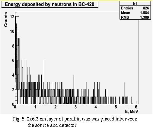
Cf-252 neutron source was presented as spherical source (2 cm in diameter) which emitts neutrons from the surface in 4pi. Also material of plastic scintillator was simulated and response function was obtained. The total number of neutrons emitted by source (670000 n) was fitted to experimental data. In this case experimental counting rate (w/o any attenuator) was 2700 cpm. Simulated counting rate was 2581 "cpm". It was supposed that Cf-252 emitts neutrons only. So, if we find the difference in counting rates wrt attenuator materials, we will be able to say what is percentage of gamma-rays our Cf source emitts. Spectrum of netrons simulated can be found blow.
(i) layer of steel (2.5 cm) passes 92% of the incident neutron flux (81% of total flux in experiment - 72.9% n & 8.1% (or whatever))
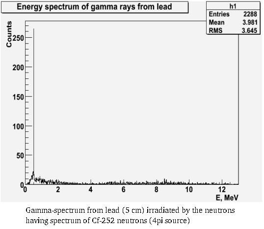
(ii) layer of lead (5 cm) passes 89.2% of the incident neutron flux (30% of total flux in experiment - 26.76% n & 3.24% )
(iii) layer of paraffin wax (6.3 cm) passes 44.2% of the incident neutron flux (81% of total flux in experiment - 35.8% n & 45.2% )
(iv) layer of paraffin wax (2x6.3 cm) passes 32% of the incident neutron flux (2.6% of total flux in experiment - 0.83% n & 1.77% )
Analysis
Properties of Materials used
Steel
Zeff = 26 and =8.02
Atomic composition for AISI 304) in %
| Element | % |
|---|---|
| Si | 1 |
| Cr | 19 |
| Mn | 2 |
| Fe | 68 |
| Ni | 10 |
Lead
Z =92 density = 11.35
Paraffin
Zeff=
according to http://ptcl.chem.ox.ac.uk/MSDS/PA/paraffin.html
density = 0.9
Photon Mass Attenuation Lengh
= attenuation length material density
Steel Calculation/Simulation
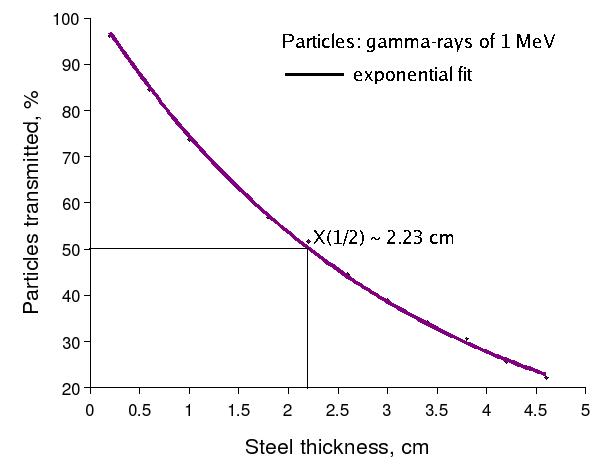
(i) A 1 MeV photon has
The photon intensity is attenuated such that
The half length is the distance needed to reduce the photon intensity in half
Therefore
In the case of steel:
So if the Californium source were just 1 MeV photons then I would expect a 2.5 cm thick steel wall to drop the rate by at least a factor of 2. In reality the photons from Cf-252 are a distribution of energies so we would need to use a montecarlo to make a more accurate prediction. All that can be concluded at this time is that a drop in rate from 2700 to 2200 counts per minute corresponds to a 19% drop in rate which indicates that the particles causing light in the scintillator are not just 1 MeV photons. One can conjecture that because the photon distribution from CF-252 contains more photons at energies below 1 MeV than above that there must be other particles besides photons (probably neutrons) making a signal in the scintillator.
(ii) Simulation of half-length value in the case of 1 MeV -rays passing thru the steel. GEANT4 was used, 0.5 cm cut was applied for , and
The difference between simulated value of half-length and calculated one is about 32.74% (??)
Lead Calculation/Simulation
(i) A 1 MeV photon has
Compare to: http://physics.nist.gov/PhysRefData/XrayMassCoef/ElemTab/z82.html
In the case of lead:
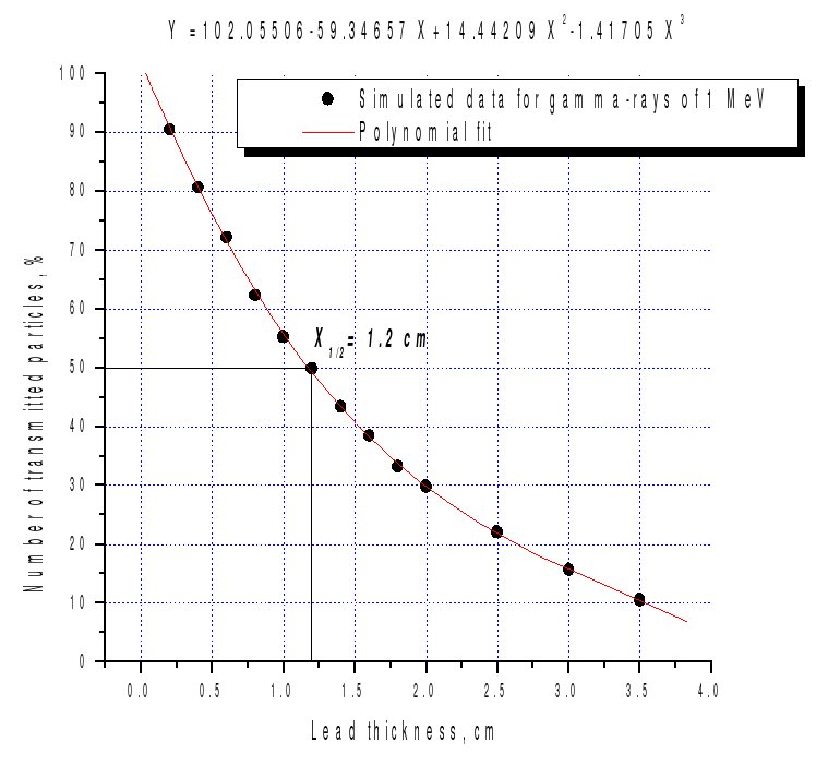
(ii) Simulated attenuation half-length of 1 MeV -rays via lead (GEANT4, default cuts).
The difference between simulated and calculated values of half-length in the case of lead is about 30% (?)
(iii) The percentage of particles passed thru the lead of thickness 0.855 cm in the case new cuts values:
| Particle | Cut | % | Cut | % | Cut | % | Cut | Cut | % | |
|---|---|---|---|---|---|---|---|---|---|---|
| -rays | 0.5 m | 0.5 nm | 1cm | 10 cm | 1 m | |||||
| 0.5 m | 0.5 nm | 1 cm | 10 cm | 1 m | ||||||
| 0.7 m | 60.74 | 0.7 nm | 60.96 | 1 cm | 60.78 | 10 cm | 60.04 | 1 m | 60.32 |
Paraffin Calculation/Simulation
(i) Assume a 1 MeV photon has
Then
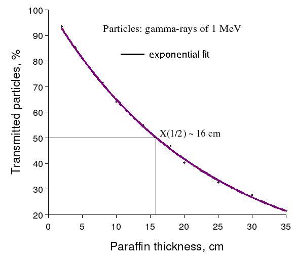
(ii) Simulation of half-length value in the case of 1 MeV -rays passing thru paraffin (C - 85.1395%, H - 14.8605%).
GEANT4 was used, 0.5 cm cut was applied for , and
The difference between simulated value of half-length and calculated one is about 35.87% (??)
Neutron Attenuation
Simulation of neutron attenuation
1. Neutron spectrum from Cf-252 source (http://hep.uchicago.edu/atlas/electr/Rad_testing/Glink_radtest.pdf)
This figure was taken from paper "Neutron Irradiation Test of an S_LINK-over-G-link System" by K. Anderson, J. Pilcher, H. Wu, E. van der Bij, Z. Meggyesi, J. Adams.
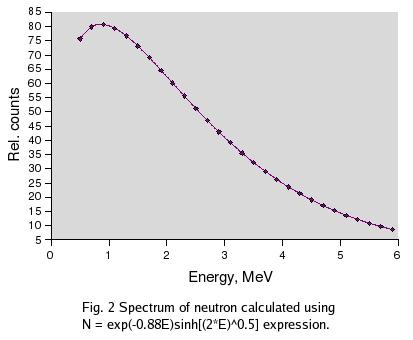
2. Spectrum of neutrons emitted according to the formula
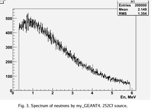
3. Spectrum of neutrons simulated using GEANT4 code.
The number of events processed is .
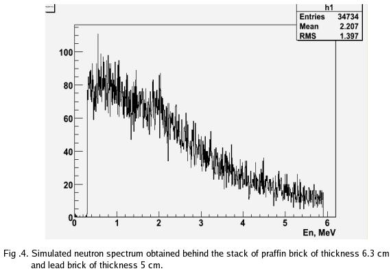
4. Simulated spectrum of neutrons attenuated by paraffin of thickness 6.3 cm and lead of thickness 5 cm.
The number of events processed is . With only 3.5e4 events remaining the simulation would predict that the 6 cm thick paraffin plus 5 cm of lead block 83% of the nuetrons
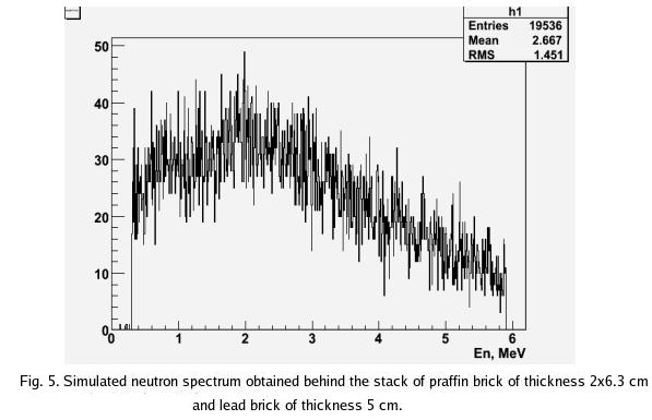
5. Simulated spectrum of neutrons attenuated by paraffin of thickness 2X6.3 cm and lead of thickness 5 cm.
The number of events processed is .
References
W. Manhart, Evaluation of the CF-252 fission neutron spectrum for between 0 and 20 MeV., Report IAEA-TECDOC-410, IAEA, Vienna, 1987, pg 158.
Long, A. B.; Wehring, B. W.; Wyman, M. E., Physical Review, vol. 188, Issue 4, pp. 1948-1957
