Difference between revisions of "JB DAQ"
| Line 28: | Line 28: | ||
==Dead time of the GG800-01 Octal Gate and Delay Generator== | ==Dead time of the GG800-01 Octal Gate and Delay Generator== | ||
| − | When an input receives 2 or more pulses over a duration less than or equal to the delay + | + | When an input receives 2 or more pulses over a duration less than or equal to (the delay) + |
| − | + | (output pulse width) + (20 ns), '''only''' the final pulse to reach the input will appear in the delayed output signal. | |
Revision as of 22:14, 17 May 2016
Back JB Analysis
DAQ commands
Source CODA and ROOT
source ~/CODA/2.6.2/setup
source /home/daq/src/root/root-5.34.00/bin/thisroot.csh
Run the bash script titled 'jeff', which takes the run number as an argument. This script will automatically convert the .dat file to a .root file and then open it in root. The script: File:Jeff.txt.
bash jeff 4716
The first index of evt.TDC1190 is the hit #. The second index increases consecutively with TDC channel number, but the index starts from 1, while the TDC channels start at 0.
Common ROOT plot commands for copy-past:
First hit minus second hit:
R1DC->Draw("(evt.TDC1190[2][1]-evt.TDC1190[1][1])")
PMT difference:
R1DC->Draw("(evt.TDC1190[1][2]-evt.TDC1190[1][3])/10","evt.TDC1190[1][2]!=0 && evt.TDC1190[1][3]!=0 && evt.TDC1190[1][1]!=0")
PMT Sum, where evt.TDC1190[1][1] is the trigger:
R1DC->Draw("(evt.TDC1190[1][3]/10+evt.TDC1190[1][2]/10)/2-evt.TDC1190[1][1]/10>>PMTSum(1000,-500,500)","evt.TDC1190[1][2]!=0 && evt.TDC1190[1][3]!=0 && evt.TDC1190[1][1]!=0")
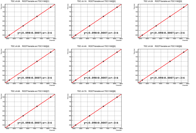
TDC Calibration
The data was collected by taking the channel difference between two pulses with a delay of 500,600,700, and 800 ns.
Miscellaneous
Pace of signal
The pace of a signal in a 223/U cable is 1.5 ns/ft.
Dead time of the GG800-01 Octal Gate and Delay Generator
When an input receives 2 or more pulses over a duration less than or equal to (the delay) + (output pulse width) + (20 ns), only the final pulse to reach the input will appear in the delayed output signal.
