Difference between revisions of "Instruments and Equipments"
| (7 intermediate revisions by the same user not shown) | |||
| Line 1,311: | Line 1,311: | ||
| + | == Specifications == | ||
| + | |||
| + | [[File:hrrl_cam_gige_specs.png | 700 px]] | ||
| + | |||
| + | == Start Camera == | ||
| + | |||
| + | Start->All Programs-> Allied Vision Technologies | ||
| + | |||
| + | For first time start "GigEIPConfig" to acquire IP addrees. | ||
| + | |||
| + | To use camera start ""GigEViewver". | ||
| + | |||
| + | [[File:hrrl_cam_gige_start_1.png | 400 px]] | ||
| + | |||
| + | |||
| + | [[File:hrrl_cam_gige_start_2.png | 400 px]] | ||
| − | |||
== Triggering == | == Triggering == | ||
| Line 1,318: | Line 1,333: | ||
The User Trigger pulse width should be at least three times the width | The User Trigger pulse width should be at least three times the width | ||
of the Trigger Latency | of the Trigger Latency | ||
| + | |||
| + | Trigger latency: 2µs for non-isolated I/O, 10µs for isolated I/O | ||
| + | |||
| + | Trigger jitter: ±20ns for non-isolated I/O, ±0.5µs for isolated I/O | ||
| + | |||
| + | [[File:HRRL_GIGE_Cam_Trig_sig_def.png | 500 px]] | ||
| + | |||
| + | |||
| + | == Camera Pin Connections == | ||
| + | |||
| + | [[File:HRRL_GIGE_Cam_Pin_Con_def.png | 500 px]] | ||
| + | |||
| + | |||
| + | |||
| + | ===Camera In 1 and Camera In 2=== | ||
| + | |||
| + | Input signals allow the camera to be synchronized to an external event. The camera can | ||
| + | be programmed to trigger on the rising edge, falling edge, both edges, or level of this | ||
| + | signal. The camera can also be programmed to capture an image at some programmable | ||
| + | delay time after the trigger event. | ||
| + | |||
| + | Camera In 1 is isolated and should be used in noisy environments to prevent false | ||
| + | triggering due to ground loop noise. Camera In 2 is non-isolated and can be used when | ||
| + | a faster trigger is required and when environmental noise is not a problem. | ||
| + | |||
| + | |||
| + | ===Camera Out 1 and Camera Out 2=== | ||
| + | |||
| + | These signals only function as outputs and can be configured as follows: | ||
| + | |||
| + | Exposing ----- Corresponds to when camera is integrating light. | ||
| + | |||
| + | Trigger ----- Ready Indicates when the camera will accept a trigger signal. | ||
| + | |||
| + | Trigger ----- Input A relay of the trigger input signal used to “daisy chain” the trigger signal for multiple cameras. | ||
| + | |||
| + | Readout ----- Valid when camera is reading out data. | ||
| + | Imaging ----- Valid when camera is exposing or reading out. | ||
| + | Strobe ----- Programmable pulse based on one of the above events. | ||
| + | GPO ----- User programmable binary output. | ||
| + | |||
| + | Any of the above signals can be set for active high or active low. | ||
| + | |||
| + | Camera Out 1 is isolated and should be used in noisy environments. Camera Out 2 is non- | ||
| + | isolated and can be used when environmental noise is not a problem and when faster | ||
| + | response is required. | ||
| + | Camera Out 1 will require a pull up resistor of greater than 1Kohm to the user’s 5V logic | ||
| + | supply. | ||
| + | See Trigger Schematics in Addendum for wiring information. | ||
| + | |||
| + | ===RS-232 RXD and RS-232 TXD=== | ||
| + | These signals are RS-232 compatible. These signals allow communication from the host | ||
| + | system via the Ethernet port to a peripheral device connected to the camera. Note that | ||
| + | these signals are not isolated and therefore careful attention should be used when | ||
| + | designing cabling in noisy environments. | ||
| + | Isolated Ground | ||
| + | Isolated Ground must be connected to the user’s external circuit ground if Sync Input 1 | ||
| + | or Sync Output 1 is to be used. | ||
| + | ===Signal Ground=== | ||
| + | Signal Ground must be connected to the user’s external circuit ground if Camera Input 2 | ||
| + | or Camera Output 2 is to be used or if the RS-232 port is to be used. Note that Signal | ||
| + | Ground is common with Power Ground however it is good practice to provide a separate | ||
| + | ground connection for power and signaling when designing the cabling. | ||
| + | ===Video Iris=== | ||
| + | This signal can be used to drive the video input of a video iris lens. See Addendum. | ||
| + | |||
| + | ===Reserved=== | ||
| + | These signals are reserved for future use and should be left disconnected. | ||
| + | |||
| + | |||
| + | |||
| + | |||
| + | |||
| + | |||
| + | [[Positrons]] | ||
Latest revision as of 22:47, 11 June 2012
Some Important Parameters
Dipole vacuum chamber width is mm
Magnets
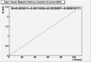
Type 1 Quad (also Quad2A )
Measurement on Magnetic field as a function of current dB/dI
Data File: File:Magnet T1Quad data.txt
ROOTSYS file to analyze this data, create figure and fit: File:Magnet T1Quad cpp.C
Figure and Fit:
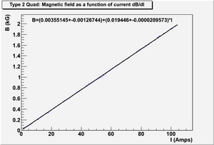
Type 2 Quad (also Quad2T )
Measurement on Magnetic field as a function of current dB/dI
The thickness of Quad2T (include magnetic shielding) is 15 cm.
Length of the pole face of Quad2T in z direction is 8 cm.
Data File: File:Magnet T2Quad data.txt
ROOTSYS file to analyze this data, create figure and fit: File:Magnet T2Quad cpp.C
Figure and Fit:
Magnet Mappings
Dr. Chouffani's Note
Second Mapping of Quadruple Magnets
Power supplies
ZUP
User manuals: File:Zup-user-manual.pdf
Other documents:
GENESYS
File:GenesysTM 750W-1500W-manual.pdf
Flag
Light on the flag
5 VDC. Brown and orange wires are for the light.
Camera on the Flag
12 V. Black and white wires are for the camera.
Air gate on the Flag
Open at 17 V, close at 7 V. Red and green wires are for the air gate.
Red = +17 V and Green = ground?
Green is connected to negative.
Order Power Supplies
| Parts | Use | Quantity | Price ($) | Link |
| 18 VDC PS | Flag Air Gate | 2-3 | $23.5 | 18V |
| 5 VDC PS | Flag Light | 2-3 | $14.22/$15.44 | 5V 1.2A / 5V 2A |
| 12 VDC PS | Flag Camera | 1-2 | $15.44 | 12V 0.83A |
| Female Crimp | Connection | 50 | $5.80 (for 50) | Female Crimp |
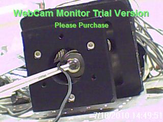
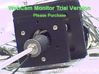
Current Camera dimension
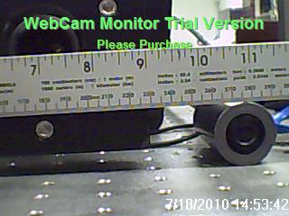
Current camera in the flag is placed in the cylindrical tube of the flag. Camera can be slided into the flag, and the distance can be controlled. Camera itself is cylindrical shaped, and placed into a cylindrical tube. The tube has 2 cm of inner diameter and 3 cm of outer diameter. Camera has 2 cm diameter.
JAI Camera
software download
http://www.jai.com/EN/CameraSolutions/Download/Pages/JAI_SDK_and_control_tool.aspx
http://www.1stvision.com/cameras/gige-camera-accessories.html
Cable
Part Number: CB-AVT-I/O-xx
Color Coding
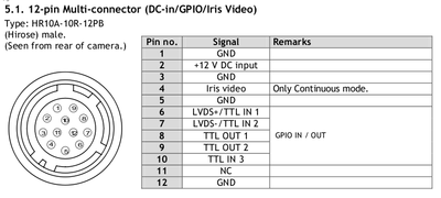
PIN#               Color
1..................Brown
2..................Red
3..................Orange
4..................Yellow
5..................Green
6..................Blue
7..................Violet
8..................Gray
9..................White
10.................Pink
11.................Light Green
12.................Black
Shell..............Drain Wire
Rev.3 4/6/10
Hardware Triggering The Camera
Pulse signal need to be send to "TTL IN 1" (pin# 6, Blue), "TTL IN 2" (pin# 7, Violet) or "TTL IN 3" (pin# 10, Pink).
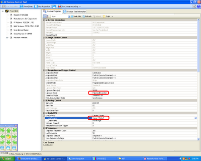
At JAI Camera Control Tool, set
c) Acquisition and Trigger COntrol:
"exposure mode" -> "Pulse-width control"
e) Digital I/O:
"Line Selector" -> "Line Source" -> "Hirose TTL In 1" (or In 2 and In3, depending on wich TTL In signal is being sended.)
JAI Camera Control
Controlling the Camera with Labview
169.254.1.106
134.50.203.196
Third Party Software for JAI GigE Vision Cameras:
National Instruments - JAI GigE Vision cameras are compatible with NI's Vision Acquisition Software and related image processing modules, including integration with the LabVIEW graphical programming environment.
NI Machine Vision Software
National Instruments has been a leader in machine vision and image processing for nearly a decade and currently supports thousands of different cameras. To acquire, display, save, and monitor images from cameras, use NI Vision Acquisition software, which is included with all NI frame grabbers and sold separately for FireWire and Gigabit Ethernet image acquisition. To process images, NI Vision software comes in two different packages: the Vision Development Module and NI Vision Builder for Automated Inspection (AI). The Vision Development Module is a collection of hundreds of vision functions for programmers using NI LabVIEW, NI LabWindows/CVI, C/C++ or Visual Basic. Vision Builder AI is an interactive software environment for configuring, benchmarking and deploying machine vision applications without programming. Both software packages work with all NI Vision frame grabbers and the NI Compact Vision System.
Labview error message
It looks like the NI software from 2009 was downloaded. There are 2 more recent versions. Perhaps if we use the latest software the error message will go away?
http://joule.ni.com/nidu/cds/view/p/id/2137/lang/en
OTR with Al
File:M.Castellan NIM A357 1995 pp231.pdf
Preferred camera:
http://www.ptgrey.com/products/flea2/flea2.pdf
saves images in ASCI format
OTR
OTR target is 1.25’’ in diameter (31.75 mm). OTR target is 10 thick Aluminium.
6 Way Cross
Diameter of the window: 3 inches.
Distance from the 6-way-cross to the floor (Not from the center, but from the bottom window to the floor.): inches = 94.615 cm.
The distance from the Center of HRRL beam pipe to the floor is: 106.3 cm
From the center of the 6-way cross to quartz window: 11.685 cm
The distance from the center of the OTR target (also the center of the 6-way cross) to the closest position we place our first lenses is 13 cm.
Edge to edge OTR cone diameter size ( angle, ) at this distance is 2.665 cm.
Optics for Emittance Measurement in Feb 2010
Polarizer
Link: [3]
Features
N-BK7 Protective Window AR Coated for Visible Range (400 - 700 nm) High Polarization Efficiency: >99% (see the Plots Tab for Extinction Ratio Data) 0.3 mm Thick Dichroic Polarizing Film Scratch Dig: 40-20
Iris
SM2D25D - Ring-Activated SM2 Iris Diaphragm: [4]
Item #         Minimum Aperture            Maximum Aperture       Mechanism
SM2D25D        Ø1 mm (Ø0.04")              Ø25 mm (Ø0.98")        Ring
Ring actuated Irises are designed for integration into a 60 mm cage assembly, where the movement of a lever actuated iris would be hampered by the cage rods.
Price: $75.50
Lens
Diameter: 5 cm.
We can use 3 lens system to hold image directly at the sensing area of the CCD camera. Sensing are of the JAI CCD camera is 6.49(h) x 4.83 (v) mm and field of view of our interest has a diameter of 1 inch.
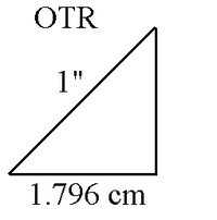
Since OTR is placed 45 degree to vertical plane, one of the dimension of the OTR image actually is 1.796 cm. If we put this to vertical dimension of the camera and put the other dimension of image on the horizontal dimension of the camera, the magnifications we need to hold the view of our interest on the 50% of the sensing area of the camera will be:
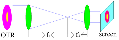
HRRL Emittance Optics Lay Out:
In this telescope system magnification will be:
So, we need to pick 2 lenses with optical length satisfy above ration. From the lower port of the 6-way cross the the floor is 94.6 cm. So, we have 90 cm place to place our camera system. So, I suggest we order camera with focal lens of 50 cm, 20, and 6, cm. These pieces can produce magnification that is small enough for experiment.
To avoid delay of experiment due to possible miscalculation, it is prudent to order 2 more lenses. One of them should be focusing and other one should be defocusing. In that case we can extend our optics as shown in following 2 figures;
Lenses for Basic Optical System Design:
| Code | Quantity | Diameter (inches) | Focal Length (cm) | Coating | Price for Each ($) | link |
| LB1723-A - N-BK7 Bi-Convex Lens | 1 | 2 | 6 | ARC: 350-700 nm | 30 | [5] |
| LB1630-A - N-BK7 Bi-Convex Lens | 1 | 2 | 10 | ARC: 350-700 nm | 29 | [6] |
| LB1909-A - N-BK7 Bi-Convex Lens | 1 | 2 | 50 | ARC: 350-700 nm | 29 | [7] |
Sub Total Price: $88
Lenses for Extended Optical System Design (Only for Extended Part):
| Code | Quantity | Diameter (inches) | Focal Length (cm) | Price for Each ($) | link |
| LB1199 - N-BK7 Bi-Convex Lens | 1 | 2 | 20 | 29 | [8] |
| LD1613-A - N-BK7 Bi-Concave Lens | 1 | 1 | -10 | 25.90 | [9] |
Sub Total Price: $ 54.9
Optical Test
| Code | Quantity | Diameter | Focal Length (mm) | Price for Each ($) | link |
| AX76654 | 1 | 51 mm | 50 | 12.5 | [10] |
| AX76960 | 1 | 51 mm | 65 | 13.5 | [11] |
| AX27361 (6 lens) | 1 | 50 mm | +-167,+-200,+500,-333 | 11.00 | [12] |
| AX937793 | 1 | 50 mm | 100 | 4.1 | [13] |
| AX937795 | 1 | 50 mm | 200 | 3 | [14] |
Sub Total: $44.1 ($30.87, if 30% off)
Cage System ($515.7)
Cage Assembly Rod
| Code | Quantity | Length (inches) | Length (cm) | Price for Each ($) | link |
| ER2 | 4 | 2 | 5.08 | 5.9 | [15] |
| ER12 | 4 | 12 | 30.48 | 16.1 | [16] |
| ER18 | 4 | 18 | 45.72 | 25.1 | [17] |
Sub Total Price: $188.4
60 mm Cage Plates
| Code | Quantity | Price for Each ($) | link |
| LCP01 | 3 | 31.3 | [18] |
| LCP01T | 3 | 35.50 | [19] |
Sub Total Price: $164.9
Dear Sadiq,
The LCP01T can hold 2" lens.  The maximum thickness for the optics would be 17.8mm (the part in contact with the retaining ring).
You can find the drawing for the part at http://www.thorlabs.com/Thorcat/21400/21473-E0W.pdf
Please let me know if you have any further questions.
Best Regards
Jeremy Low
Technical Support
Polaris Low drift mirror mount, one of 2000 new products in V20!
Get your catalog at www.thorlabs.com/Catalog
THORLABS Inc.
T (973) 579-7227 | F (973) 300-3600
www.thorlabs.com
- Show quoted text -
LCP02 - 30 mm to 60 mm Cage Plate Adapter
| Code | Quantity | Price for Each ($) | link |
| LCP02 | 1 | 37.8 | [20] |
Sub Total Price: $37.8
LCP03 - 60 mm Blank Cage Plate
| Code | Quantity | Price for Each ($) | link |
| LCP03 | 1 | 32.6 | [21] |
Sub Total Price: $32.6
Cage Assembly Platforms
| Code | Quantity | Price for Each ($) | link |
| LCPM | 1 | 85.10 | [22] |
Sub Total Price: $85.1
LCPA1 - 60 mm Cage Alignment Plate
| Code | Quantity | Price for Each ($) | link |
| LCPA1 | 1 | 15.3 | [23] |
Sub Total Price: $15.3
Total for Cage System: $524.1
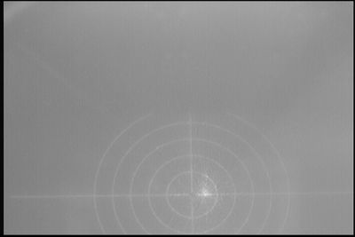
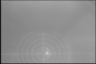
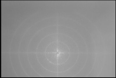
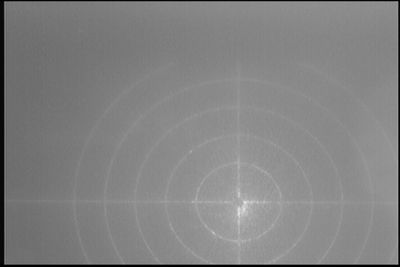
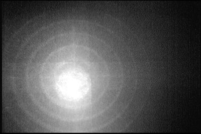
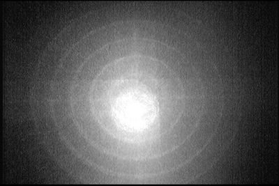
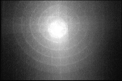
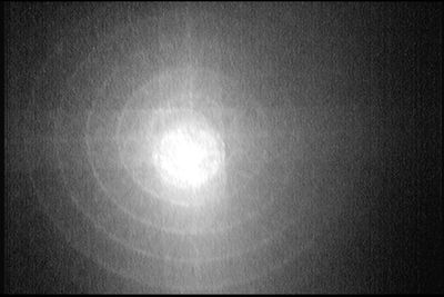
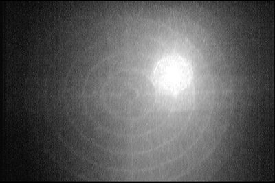
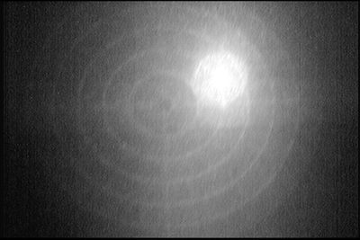
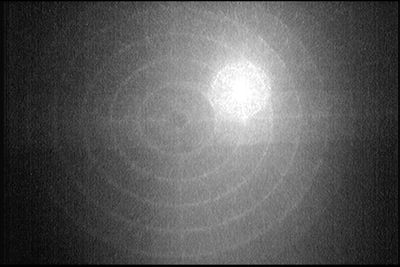
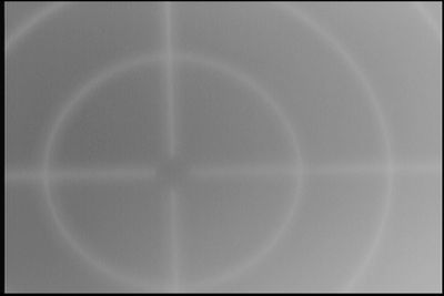
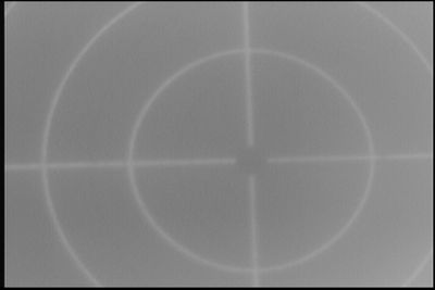
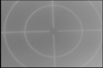
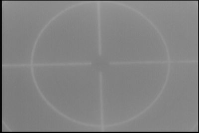
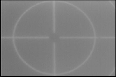
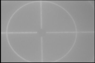
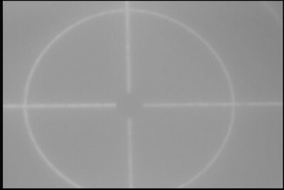
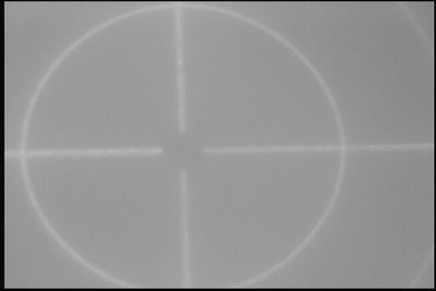
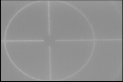
Imaging System Test
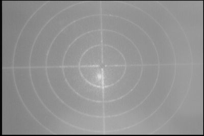
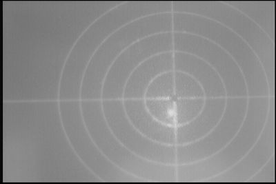
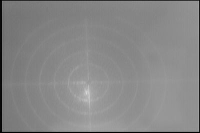
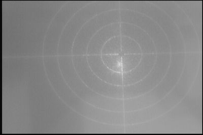
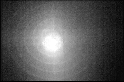
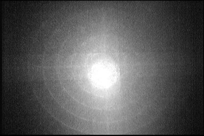
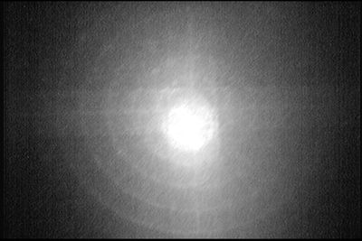
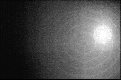
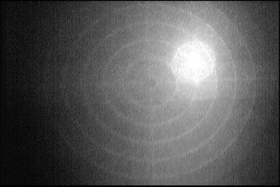
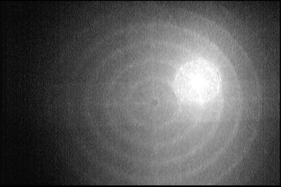
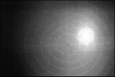
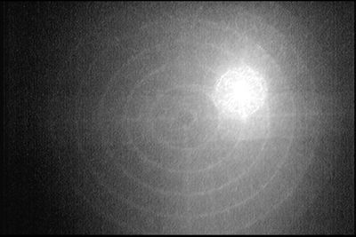
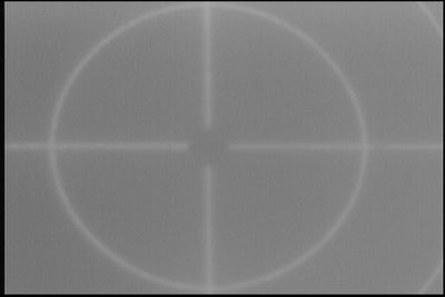
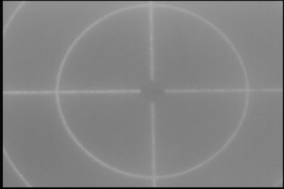
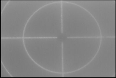
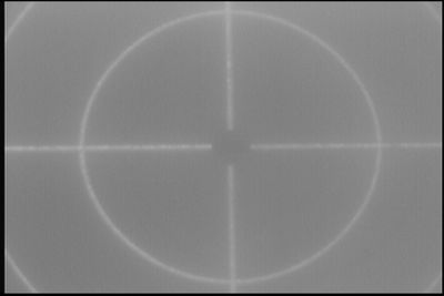
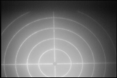
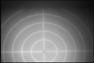
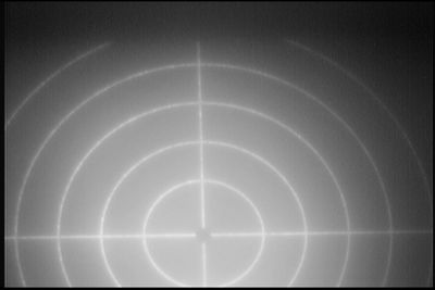
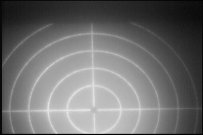
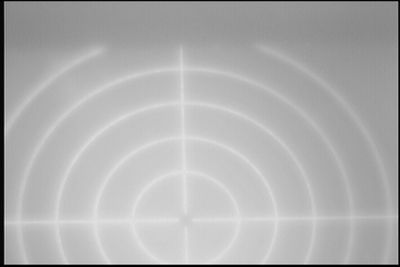
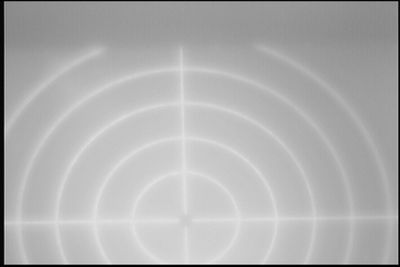
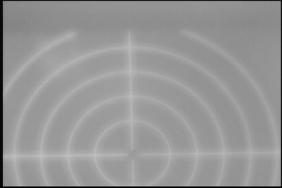
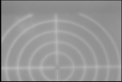
Cage system were constructed, and 3 lenses with focal length of 500 mm, 100 mm, and 65 mm used to take image.
Out most ring on the target has a diameter of 27 mm.
Lights and Laser on
Following images are taken within distance of 45 cm (from target to CCD sensor).
Dr. Kim's suggestion:
Dear Sadiq,
Good Job!
If you have some free time, please would you try to improve brightness of the captured image?
As you can see, the captured rings are somewhat dark now.
If it is needed, you may install a small LED illuminator toward the screen and a light-shielding box around the cage.
The bigger lens are also helpful to improve brightness.
Sincerely yours,
Yujong Kim
Following are images in dark, and laser on the target
Lights on,Laser off
Inner most circle has a diameter of 7 mm.
Lights off,Laser off, Blue LED on
Lights on,Laser off, Blue LED on
Optics for Alinement
4 mirrors (with mounts and stand )
Mount for Ø1" Optics with Visible Laser Quality Mirror
Price: $105.35
http://www.thorlabs.com/thorProduct.cfm?partNumber=KM100-E02
Tot for 4: $421.4
4 (at lest, 6 preferably) Irises (with stand )
Post-Mounted Iris Diaphragm, Ø20.0 mm Max Aperture
Price: $44.00
http://www.thorlabs.com/thorProduct.cfm?partNumber=ID20
Tot for 4: $176
1 focus and 1 defocus lens (with mounts and stand )
N-BK7 Bi-Convex Lenses (AR Coating: 350-700 nm)
http://www.thorlabs.com/thorProduct.cfm?partNumber=LB1945-A
N-BK7 and N-SF11 Bi-Concave Lenses
Price: $29.10
LD1464 - N-BK7 Bi-Concave Lens, Ø25.4 mm, f = -50.0 mm, Uncoated
http://www.thorlabs.com/thorProduct.cfm?partNumber=LD1464
Price: $18.90
Tot: 48
2 Translating Lens Mount for Ø1" Optics
http://www.thorlabs.com/thorProduct.cfm?partNumber=LM1XY
Price: $133.70
For 2: $267.4
1 optical Rail
http://www.thorlabs.com/thorProduct.cfm?partNumber=RLA1200
Price: $69.30
Optical Post
Stainless Steel Optical Posts: Ø1/2", Ø12.7 mm, and Ø12 mm
http://www.thorlabs.com/NewGroupPage9.cfm?ObjectGroup_ID=1266
We Want 4: Ø1/2" x 4" Stainless Steel Optical Post
Price: $5.87
http://www.thorlabs.com/thorProduct.cfm?partNumber=TR4
Tot: 23.48
Ø1/2" Utility Post Holders
http://www.thorlabs.com/NewGroupPage9.cfm?ObjectGroup_ID=1268
We want 10: Post Holder, L = 4.00"
http://www.thorlabs.com/thorProduct.cfm?partNumber=PH4
Price: $9.17
Tot for 8: $91.7
Post Holder Bases
http://www.thorlabs.com/NewGroupPage9.cfm?ObjectGroup_ID=47
2 of BA1 - Mounting Base, 1" x 3" x 3/8" : http://www.thorlabs.com/thorProduct.cfm?partNumber=BA1
Price: $5.60
For 2: $11.2
2 of BA1R - Magnetic Mounting Base, 1" x 3" x 3/8"
Price: $11.20
For 3: $33.6
Total
Energy Slit
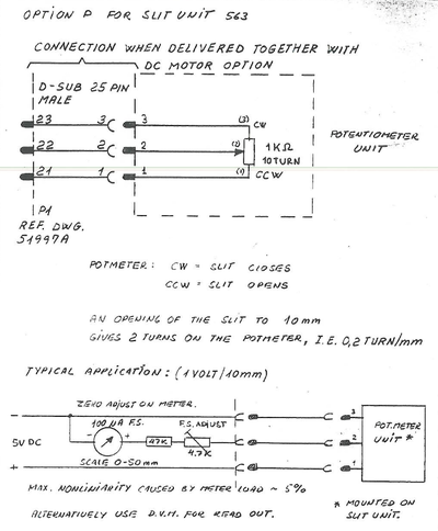
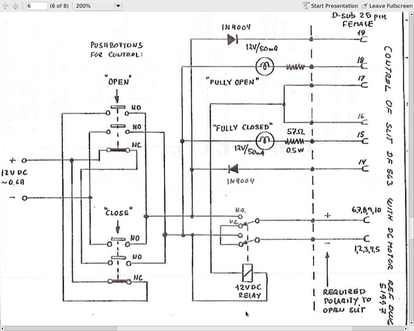
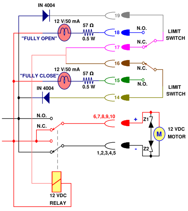
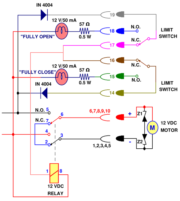
Danfysik water cooled Slit model 563, document from vendor:
File:DanfysikSlit563 vandor.pdf
Danfysik water cooled Slit model 563:
Fact Sheet:
File:DanfysikSlit563 FactSheet.pdf
Parts to build control circuit
This list is removed so that Dr. Forest won't get confused.
Slit-Aperture vs. Potentiometer-Resistance
Slits has two side: Copper and White metal. There are resistors connected the bolts on the copper side. White metal side has smaller aperture. Thus white metal side should face up stream of the beam line, since this side define beam aperture.
Copper side - Downstream side
This copper side, this measurement is useless.
| Slit aperture size (mm) | Resistance at Potentiometer (k) |
| 39.78 0.1 | 9.38 0.005 |
| 37.64 0.1 | 8.97 0.005 |
| 35.71 0.1 | 8.48 0.005 |
| 33.76 0.1 | 8.00 0.005 |
| 31.59 0.1 | 7.49 0.005 |
| 29.86 0.1 | 7.00 0.005 |
| 27.62 0.1 | 6.48 0.005 |
| 25.83 0.1 | 6.00 0.005 |
| 23.62 0.1 | 5.50 0.005 |
| 21.57 0.1 | 4.99 0.005 |
| 19.33 0.1 | 4.50 0.005 |
| 17.32 0.1 | 3.99 0.005 |
| 15.22 0.1 | 3.50 0.005 |
| 12.88 0.1 | 2.99 0.005 |
| 10.42 0.1 | 2.486 0.005 |
| 8.66 0.1 | 1.999 0.005 |
| This is smallest aperture, yet it is not closed. I don't have tool to measure it. | 0.147 0.005 |
White metal side - Upstream side
This side has white metal, has smaller aperture. This aperture closes. This side should face upstream side of the beam line.
Measurement
| Slit aperture size (mm) | Resistance at Potentiometer (k) |
| 37.60 0.1 | 9.40 0.01 |
| 35.80 0.1 | 9.20 0.01 |
| 34.95 0.1 | 9.00 0.01 |
| 34.25 0.1 | 8.80 0.01 |
| 33.38 0.1 | 8.60 0.01 |
| 32.49 0.1 | 8.40 0.01 |
| 31.80 0.1 | 8.20 0.01 |
| 31.03 0.1 | 8.00 0.01 |
| 30.37 0.1 | 7.80 0.01 |
| 29.31 0.1 | 7.60 0.01 |
| 28.55 0.1 | 7.40 0.01 |
| 27.69 0.1 | 7.20 0.01 |
| 26.94 0.1 | 7.00 0.01 |
| 26.10 0.1 | 6.80 0.01 |
| 25.33 0.1 | 6.60 0.01 |
| 24.51 0.1 | 6.40 0.01 |
| 23.48 0.1 | 6.20 0.01 |
| 22.66 0.1 | 6.00 0.01 |
| (21.91+21.86+21.92,21.99+22.01+21.85+21.87+21.94)/8 = 21.92 0.1 | 5.80 0.01 |
| 21.43 0.1 | 5.70 0.01 |
| 21.02 0.1 | 5.60 0.01 |
| 20.56 0.1 | 5.50 0.01 |
| 20.26 0.1 | 5.40 0.01 |
| 19.72 0.1 | 5.30 0.01 |
| 19.35 0.1 | 5.20 0.01 |
| 18.91 0.1 | 5.10 0.01 |
| 18.68 0.1 | 5.00 0.01 |
| 18.09 0.1 | 4.90 0.01 |
| 17.83 0.1 | 4.80 0.01 |
| 17.42 0.1 | 4.70 0.01 |
| 16.93 0.1 | 4.60 0.01 |
| 16.47 0.1 | 4.50 0.01 |
| 16.06 0.1 | 4.40 0.01 |
| 15.60 0.1 | 4.30 0.01 |
| 15.23 0.1 | 4.20 0.01 |
| 14.96 0.1 | 4.10 0.01 |
| 14.47 0.1 | 4.00 0.01 |
Measurement Data
File:Energy Slit Size-vs-PotReistance.txt
Slit aperture  Resistance at
size (mm) 	Potentiometer (kΩ)
with error     with error
---------------------------
37.60  0.1 	9.40  0.01
35.80 	0.1 	9.20  0.01
34.95 	0.1 	9.00  0.01
34.25 	0.1 	8.80  0.01
33.38 	0.1 	8.60  0.01
32.49 	0.1 	8.40  0.01
31.80 	0.1 	8.20  0.01
31.03 	0.1 	8.00  0.01
30.37 	0.1 	7.80  0.01
29.31 	0.1 	7.60  0.01
28.55  0.1 	7.40  0.01
27.69 	0.1 	7.20  0.01
26.94 	0.1 	7.00  0.01
26.10 	0.1 	6.80  0.01
25.33  0.1 	6.60  0.01
24.51  0.1 	6.40  0.01
23.48  0.1 	6.20  0.01
22.66  0.1 	6.00  0.01
21.92  0.1 	5.80  0.01
21.43  0.1 	5.70  0.01
21.02  0.1 	5.60  0.01
20.56  0.1 	5.50  0.01
20.26  0.1 	5.40  0.01
19.72  0.1 	5.30  0.01
19.35  0.1 	5.20  0.01
18.91  0.1 	5.10  0.01
18.68  0.1 	5.00  0.01
18.09  0.1 	4.90  0.01
17.83  0.1 	4.80  0.01
17.42  0.1 	4.70  0.01
16.93 	0.1 	4.60  0.01
16.47  0.1 	4.50  0.01
16.06  0.1 	4.40  0.01
15.60 	0.1 	4.30  0.01
15.23  0.1 	4.20  0.01
14.96 	0.1 	4.10  0.01
14.47  0.1 	4.00  0.01
Slit aperture   with their
size (mm) 	 errors
with
Resistance at
Potentiometer
(kΩ)
S(mm)  R(kΩ)  er_S(mm) er_R(kΩ)
----------------------------
37.6	9.4	0.1	0.01
35.8	9.2	0.1	0.01
34.95	9	0.1	0.01
34.25	8.8	0.1	0.01
33.38	8.6	0.1	0.01
32.49	8.4	0.1	0.01
31.8	8.2	0.1	0.01
31.03	8	0.1	0.01
30.37	7.8	0.1	0.01
29.31	7.6	0.1	0.01
28.55	7.4	0.1	0.01
27.69	7.2	0.1	0.01
26.94	7	0.1	0.01
26.1	6.8	0.1	0.01
25.33	6.6	0.1	0.01
24.51	6.4	0.1	0.01
23.48	6.2	0.1	0.01
22.66	6	0.1	0.01
21.92	5.8	0.1	0.01
21.43	5.7	0.1	0.01
21.02	5.6	0.1	0.01
20.56	5.5	0.1	0.01
20.26	5.4	0.1	0.01
19.72	5.3	0.1	0.01
19.35	5.2	0.1	0.01
18.91	5.1	0.1	0.01
18.68	5	0.1	0.01
18.09	4.9	0.1	0.01
17.83	4.8	0.1	0.01
17.42	4.7	0.1	0.01
16.93	4.6	0.1	0.01
16.47	4.5	0.1	0.01
16.06	4.4	0.1	0.01
15.6	4.3	0.1	0.01
15.23	4.2	0.1	0.01
14.96	4.1	0.1	0.01
14.47	4	0.1	0.01
Linear Fit for Data
Data for 37.6 mm aperture was excluded from fit because it is far off from the straight line (manufacture claims biggest aperture is 35 mm, could be we are exceeded this value).
S(mm)  R(kΩ)  er_S(mm) er_R(kΩ)
37.6	9.4	0.1	0.01
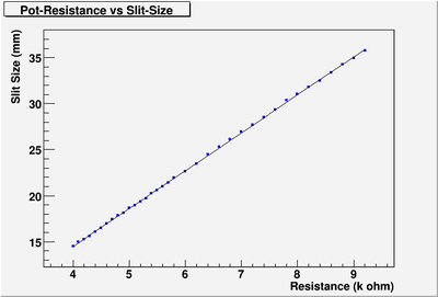
Pot resistance vs Aperture size
The fit is:
When units are mm for Slitize (S), k Resistance (R)
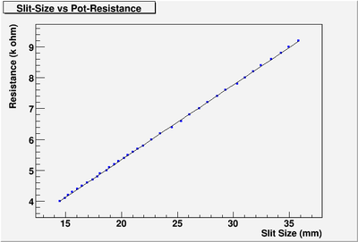
Aperture size vs Pot resistance
The fit is:
or, when units are mm for Slitize (S), k Resistance (R)
LED Display for Aperture Size
: Resistance in the Potentiometer on the Energy Slit.
: Resistance in the LED display circut.
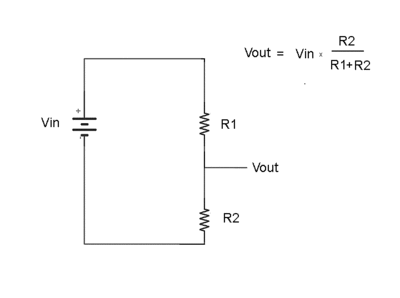
Voltage Divider
Consider the two resistors in series below
What is the ratio of to
Ohm's Law
so
is measure:
Control Circuit
Design:
Power Supply
Old PS
Old Power Supply: Max Current = 0.83 A: This PS does not have sufficient current supply. When we drive motor, we need current of 1 Amp. When the motor just started, current can go up as 1.7~1.8 Amp. So, we need PS with 12 VDC and Max current around 1.7~1.8 Amp.
New PS
Option 1
Price: $16.64.
Input:90 ~ 264VAC.
Output - 1 @ Current (Max): 12 VDC @ 1.67A
Size / Dimension: 3.5" L x 2" W x 0.85" H (89.1mm x 51mm x 21.6mm)
Power (Watts) - Max: 20 W
Option 2
http://search.digikey.com/us/en/products/ZPSA20-12/285-1747-ND/1766384
Price: $21.93.
Voltage - Output 12V
Number of Outputs 1
Power (Watts) 20W
Applications Commercial
Power Supply Type Switching (Open Frame)
Voltage - Input 85 ~ 264VAC
Mounting Type Chassis Mount
Output - 1 @ Current (Max) 12 VDC @ 1.8A
Size / Dimension 3.5" L x 2" W x 0.79" H (88.9mm x 50.8mm x 20mm)
Original Design:
Digikey order
| part | number | link |
| power supply | 1 | [25] |
| 12 vdc relay | 1 | [26] |
| LED | 10 | [27] |
| part | number | link |
| circuit breaker chip | 5 | [28] |
| MOSFET N-channel | 5 | [29] |
| zener 5V | 10 | [30] |
| capacitor 10uF | 5 | [31] |
| capacitor .22uF | 5 | [32] |
| resistor 51kohm | 5 | [33] |
| resistor 100ohm | 5 | [34] |
| resistor 1ohm 5W | 5 | [35] |
| resistor 0.036ohm | 3 | [36] |
| zener 15 V | 5 | [37] |
| diode | 5 | [38] |
| MOSFET 70 mohm | 5 | [39] |
| solenoid 12V | 1 | [40] |
Final Test
1. When fully closed, shows 0.17-0.18 cm (1.7-1.8 mm). Slit does not close fully, there is very little gap that I couldn't measure. I estimate that is around 1 mm. So, I estimate my error on the energy slit to be 2 mm at maximum.
When switch to close, "Full clos" light is on.
2. Turn the switch to open. Then the reading is getting bigger.
3. When fully opened, the "Full open" light is on. Then we need to put turn the toggle switch to center. The reading shows 3.47 - 3.52 cm (34.7 - 35.2 mm). I measured the distance between two slits. It was 3.5 cm.
I would record my readings with 2 mm error. So, biggest gap between slits would be 3.5 +- 0.2 cm.
Beam Pipe for Quad7
Need to order 2 flanges from Duniway (www.duniway.com):
1. F450-200 R
2. F458-000 N
3rd JLab Flag
The third Jlab flag does not have switch. We can not control remotely with electronically.
Applying pressure to upper gas inlet of the flag will push target holder into the 3-way cross. Without pressure, holder goes back.
We can control by gas pressure. If we have long enough pipe for gas, we can control it remotely.
JLab flag is missing one 458 (10 hole) flange. We need buy it, if we are using it.
Ion Pump
S/N: Z1109053
Model: DSD-020-5125-M
+HV Diode
Ion Pump Connector
Power Supply End
Hv connector power supply end
P/E-10KV
$50
Pump End
Hv connector pump end
V-100-X
$165
FS-105-X Ion Pump High Voltage Connector
Assembly/Connection Instructions
Media:HRRL_Ion_Pump_Connector_Pump-End_Ins.pdf
Power Supply
Varian MiniVac
Model: 929-0191
S/N: 201685
File:Ion pump HV PS Varian MiniVac 929-0191.pdf
HV Cable
We 25 meter (82 feet) long cable from control room to end of beam line the experimental room.
The current cable used on other ion pumps are from Teledyne Reynolds HV Cable.
On the cable it says "Reynolds 169-2269 C Cable". I found the cable from the company, and asked quote for 83 long cable of this kind.
P/N 167-2669 Type“C”
Inner Conductor: 19 strands TPC. AWG 16
Cable Insulation: Clear polyethylene. Dia. 0.118/2.9
Shield: No. 36 AWG.
Jacket: Polyethylene. Dia.: 0.195/4.9
Electrical: Voltage rating: 20 KVDC
Impedance: 31 Ohms
Capacitance: 48.0 PF per ft. nominal
Inductance: 0.061 µH per ft.
Wires
Accelerator side
From control room to the end of the 0 degree beamline, we need about 20 meters of wire.
2 Flags
Each Flag needs 6 wires
2 Flags at accelerator side: There is one wire with 12 small wires inside already.
Energy Slit
Energy slit needs 11 wires: Need to get it from IAC 20 meter long wire.
3rd Flag
Flag at experimental side: Need wire
Experimental Side
From Control room to the where the Annihilation target and ion pump is about 25 meter.
HV Cable
HV Cable for Ion pump.
Annihilation Target Flag
One Flags needs 6 wires.
GigE Vision Camera
Prosilica GC1290 GigE Vision Camera
S/N: 02-218A-20132
MAC:000F312098
Media:GigE_vision_camera_DataSheet.pdf
Media:GigE_vision_camera_TechMan.pdf
Media:GigE_vision_camera_InstGuide.pdf
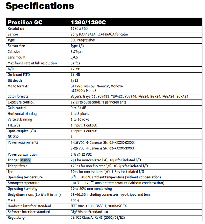
Specifications
Start Camera
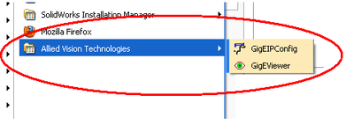
Start->All Programs-> Allied Vision Technologies
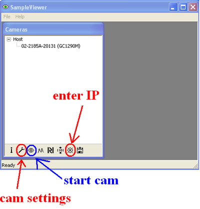
For first time start "GigEIPConfig" to acquire IP addrees.
To use camera start ""GigEViewver".
Triggering
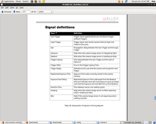
The User Trigger pulse width should be at least three times the width of the Trigger Latency
Trigger latency: 2µs for non-isolated I/O, 10µs for isolated I/O
Trigger jitter: ±20ns for non-isolated I/O, ±0.5µs for isolated I/O
Camera Pin Connections
Camera In 1 and Camera In 2
Input signals allow the camera to be synchronized to an external event. The camera can be programmed to trigger on the rising edge, falling edge, both edges, or level of this signal. The camera can also be programmed to capture an image at some programmable delay time after the trigger event.
Camera In 1 is isolated and should be used in noisy environments to prevent false triggering due to ground loop noise. Camera In 2 is non-isolated and can be used when a faster trigger is required and when environmental noise is not a problem.
Camera Out 1 and Camera Out 2
These signals only function as outputs and can be configured as follows:
Exposing ----- Corresponds to when camera is integrating light.
Trigger ----- Ready Indicates when the camera will accept a trigger signal.
Trigger ----- Input A relay of the trigger input signal used to “daisy chain” the trigger signal for multiple cameras.
Readout ----- Valid when camera is reading out data. Imaging ----- Valid when camera is exposing or reading out. Strobe ----- Programmable pulse based on one of the above events. GPO ----- User programmable binary output.
Any of the above signals can be set for active high or active low.
Camera Out 1 is isolated and should be used in noisy environments. Camera Out 2 is non- isolated and can be used when environmental noise is not a problem and when faster response is required. Camera Out 1 will require a pull up resistor of greater than 1Kohm to the user’s 5V logic supply. See Trigger Schematics in Addendum for wiring information.
RS-232 RXD and RS-232 TXD
These signals are RS-232 compatible. These signals allow communication from the host system via the Ethernet port to a peripheral device connected to the camera. Note that these signals are not isolated and therefore careful attention should be used when designing cabling in noisy environments. Isolated Ground Isolated Ground must be connected to the user’s external circuit ground if Sync Input 1 or Sync Output 1 is to be used.
Signal Ground
Signal Ground must be connected to the user’s external circuit ground if Camera Input 2 or Camera Output 2 is to be used or if the RS-232 port is to be used. Note that Signal Ground is common with Power Ground however it is good practice to provide a separate ground connection for power and signaling when designing the cabling.
Video Iris
This signal can be used to drive the video input of a video iris lens. See Addendum.
Reserved
These signals are reserved for future use and should be left disconnected.
