Difference between revisions of "IAC LeadFlourideCherenkovCrystalTests 5-09"
(→Day 1) |
(→Day 1) |
||
| Line 87: | Line 87: | ||
------------------------------------------------------------------------------------------------------------------------------------------------------- | ------------------------------------------------------------------------------------------------------------------------------------------------------- | ||
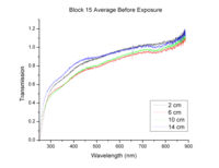
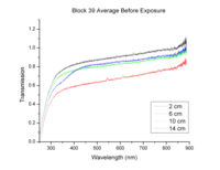
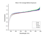
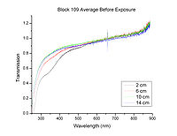
| − | 3) Irradiation batch 1:4 old ``reference'' blocks -Blocks 15, 27, 109 and 89. | + | 3) Irradiation batch 1:4 old ``reference'' blocks -Blocks 15, 27, 109 and 89. Here is the transmission before irradiation: |
[[Image:B15averagebeforeexp.jpg | 200 px]] [[Image:B39averagebeforeexp.jpg | 200 px]] [[Image:B100averagebeforeexp.jpg | 200 px]] [[Image:B109averagebeforeexp.jpg | 200 px]] | [[Image:B15averagebeforeexp.jpg | 200 px]] [[Image:B39averagebeforeexp.jpg | 200 px]] [[Image:B100averagebeforeexp.jpg | 200 px]] [[Image:B109averagebeforeexp.jpg | 200 px]] | ||
Revision as of 21:41, 12 May 2009
http://clasweb.jlab.org/wiki/index.php/Hall_A_IAC_Tests
Previous Tests: IAC_LeadFlourideCherenkovCrystalTests
Run Plan
Summary
| Task | Time Budget |
| Beam setup | 0.5 days |
| Testing 20 new blocks | 2.5 days |
| Silicon test | 1.0 day |
| Bleaching/Re-irradiation test | 0.5-1 day |
| Testing old blocks | 12 blocks/day |
- Accelerator Settings
| beam energy | 20 MeV |
| Rep Rate: | 30 Hz |
| I_peak: | 60 mA/pulse |
| pulse width: | 0.1 s (100 ns) |
Day 0
Experiment Set-up Tasks:
1) Translator table -positioned in front of 0 degree exit port and manual operation (50,000/inch).
2) Faraday Cup - positioned at z = 30 cm, clipped (alligator to BNC & grounded), connected to cable C6, terminated into Channel 1 on the scope.
3) Green pick-up loop -Sits freely atop poly blocks in front of exit window with poly spacers between loop and exit window to prevent grounding, connected to cable C7, terminated into channel 3 (?) on scope (re-check this on morning of Day 1).
4) Fluke multimeter & camera set-up for real-time temperature monitoring - camera positioned and focused, connected via cable C5 to DAQ monitor.
5) Glass plate -unable to locate small size plate on Day 0, will look again morning of Day 1. Beam spot size measurement not crucial given properly operating beam scan software.
6) Beam scan -Brian is troubleshooting this software, will show Adrianne how to use the morning of Day 1.
Day 1
Beam setup & 2-3 hours
11:25 AM -
12:00 PM -
1) Shoot glass plate at 30cm from exit port
2) Temperature test with 1 old block
- Accelerator Settings
| beam energy | 20 MeV |
| Rep Rate: | 100 Hz |
| I_peak: | 111 mA/pulse |
| pulse width: | 0.1 s (100 ns) |
23 deg C at start 33 max at finish -1 hour 40 min beam on.
Total count on Ortec counter -361931
Oscope data: C:\My Computer\Current Normalization\20090511\pbf2irradtemprun-Ch1-003.dat - pbf2irradtemprun-int.meas
3) Irradiation batch 1:4 old ``reference blocks -Blocks 15, 27, 109 and 89. Here is the transmission before irradiation:
- Accelerator Settings
| beam energy | 20 MeV |
| Rep Rate: | 100 Hz |
| I_peak: | 111 mA/pulse |
| pulse width: | 0.1 s (100 ns) |
2.5 hours beam on.
O-scope data: C:\My Computer\Current Normalization\20090511\pbf2irrad1strunday1_1-Ch1.meas-9999.dat
Day 2
1) Irradiation batch 2:4 new blocks
Blocks 200, 201, 202, 203.
Beam on: 9:15 AM
- Accelerator Settings
| beam energy | 20 MeV |
| Rep Rate: | 100 Hz |
| I_peak: | 111 mA/pulse |
| pulse width: | 0.1 s (100 ns) |
o Beam off at 1:00 PM.
o Pulse count: 1412543
o Block 100 will be used as a reference for transmission measurements for the rest of the week.
o O-scope data: C:\My Computer\Current Normalization Data\20090512\_2-Ch1-0001.dat-_2-Ch1-0843.dat
2) Irradiation batch 1 (Blocks 15, 27, 109 and 89) removed from hall (7:45 AM) and transmission measured.
Translator table origin @ exit window:
Axis 1 - 0 (beamline)
Axis 2 - -14925 (Horizontal)
Axis 3 - -111750 (Vertical)
3) Irradiation batch 3:4 new blocks -Blocks 204, 205, 206, 207.
- Accelerator Settings
| beam energy | 20 MeV |
| Rep Rate: | 100 Hz |
| I_peak: | 111 mA/pulse |
| pulse width: | 0.1 s (100 ns) |
o Beam on 1:09 PM
o 2:19 PM -no optical bleach yet. Block 89 shows gains in transmission after 2.5 hour irradiation.
o Beam off at 2:23 PM
Pulse count: 455378.
O-scope data: C:\My Computer\Current Normalization Data\20090512\_2-Ch1--0845.dat-0853.dat
o Beam on 2:28 PM
Irradiation batch \#4:&4 new blocks
Irradiation batch \#5:&4 new blocks
Irradiation {\bf batch \#2}:&4 new blocks
Bleaching of batch \#2:&24 hours
Day 3
- Accelerator Settings
| beam energy | 20 MeV |
| Rep Rate: | 30 Hz |
| I_peak: | 60 mA/pulse |
| pulse width: | 0.1 s (100 ns) |
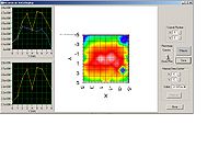
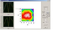
1.) Irradiate Silicon detector for 2-3 hours
Minimum ionizing particles deposit 0.19 MeV of energy /,J). If we want to irradiate particles/s, that makes J/s. Taking into account the strip size and the heat capacity of Si (19.8 J/mol/K), this makes a temperature variation of 0.045 K/min (negligeable).
2.) Irradiation PB crystal batch \#2 then Bleaching of batch #2 for 38 hours
Day 4
Irradiation batch \#6:&4 new blocks\\ Irradiation batch \#7:&4 new blocks\\ Irradiation batch \#8:&4 new blocks\\
Day 5
Irradiation {\bf batch \#2}\\ \multicolumn{2}{l}{Silicon test}\\ Day 6 -- Bleaching of batch \#2:&24h\\
