IAC LeadFlourideCherenkovCrystalTests
Radiation Exposure Tests in December for Hall A.
We will have three days of beamtime (Dec 3-5). We will use the the 25-MeV linac to direct an electron beam upon the crystals. The Lead Flouride crystals will be placed on a translator table so that each crystal can be moved individually into the beam. The crystals are 30x30x185 and are 1290g each.
We need to keep the Power below 1 Watt onto the crystal or 0.78 Gy/s for a block of 1.3 kg. We can achieve this by setting the beam parameters of the 25-MeV LINAC appropriately (cf. http://www.iac.isu.edu/facilities/25MeV_hall.html).
Here we have: P = E I
Here, [P] Watts, [E] MeV, and [I] A
- Accelerator Settings
| beam energy | 20 MeV |
| Rep Rate: | 10 Hz |
| I_peak: | 50 mA/pulse |
| pulse width: | 0.1 s (100 ns) |
Time on for one second is 1 us. and Time off is 0.999999 s The average current 0.999999 * 0 + 0.000001*50mA = 0.05 A.
P = (20 MeV) (0.05 A) = 1 Watt.
With the proviso we keep the I_peak (Instantaneous Current in the pulse) well above 5 mA (noise level) so the it can be tracked by the pick-up coil. 50 mA/pulse will do the job.
Crew: Pierre Bertin, Tony Forest, Adrianne Spilker, Amine Mestari, Syed Naeem, and Phil Cole
Status of Setup.
 Translator Table (3 degrees of freedom).
    Setup Done.  Amine and Adrianne
    DAQ/Readout
 Faraday Cups
    Setup
    DAQ/Readout
 Pickup Coil
    Setup
    DAQ/Readout
 Lead Shielding
Day 0 will be for final setup. Pierre, Tony, and Adrianne.
Day 4 and Day 5 will be used to more curing and transparency measurements.
The specifics are listed below
RunPlan:
Transparency test
A Blue light (OSRAM 24W/67 made in italy) with a wavelength range from 410 to 460 nm is used to anneal the crystals after irradiation.
A spectrometer (Ocean Optics USB4000) with a wavelength range from 200 to 1100 nm is then used to measure the transparency of crystals after optical curing.
Features of Spectrometer:
- Max sensitivity 130 photons/count at 400 nm; 60 photons/count at 600 nm
- Resolution of 0.3 (FWHM)
- Intergration times ~ 10 microseconds to 65 seconds
- 16 bit, 3 MHz A/D Converter
Deuterium Tungsten Light source emits 200-2000 nm.
Measurements
Analysis:
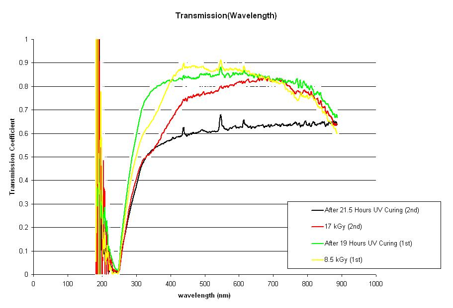
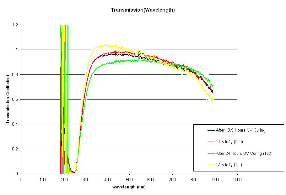
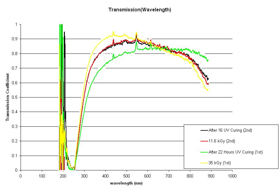
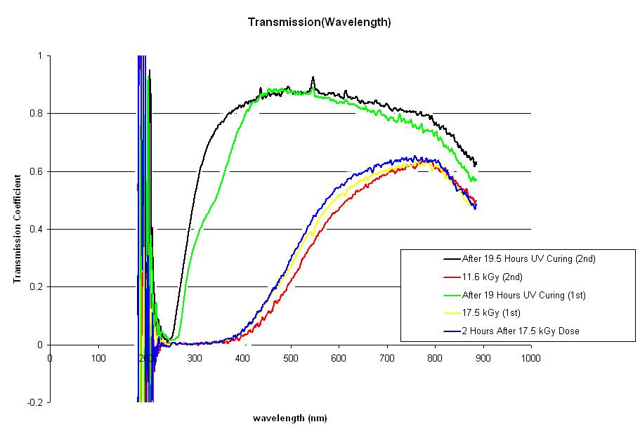
The following data is an analysis of the transmission coefficient for light incident on PbF2 crystals. The transmission coefficient is plotted as a function of wavelength. This value was evaluated using the following relationship found in Roche:
Where S( ) is the intensity spectrum of light through a PbF2 crystal at 1 cm along the length of the sample, B( ) is the intensity spectrum of the background, and R( ) is the intensity spectrum of unobstructed light. Spectra for light incident at 3 cm, 6 cm, 11 cm and 16 cm were also rendered at the time of the measurement; these have yet to be evaluated.
A Geant simulation of 20 MeV electrons impinging on a lattice of PbF2 shows that the majority of energy is deposited in the first centimeter of the sample. Since it was expected that most of the radiation damage would lie in this region, spectra rendered at 1 cm along the length of the sample were chosen for analysis before spectra rendered at further lengths.
Four measurements of each sample were made throughout this experiment. Crystals were irradiated with the 25 MeV LINAC at the Idaho Accelerator Center over intervals of 1, 2, and 4 hours. Each sample was exposed and cured with blue UV light twice. Measurements of the intensity were taken after exposure, and after blue light curing just before the next exposure. Each measurement was made twice: once with the sample resting in its original position at the time of irradiation and again with the sample tilted 90 degrees. These two measurements were averaged together. Graphs shown on this page are moving average fits binned at 20 data points per bin. A link to graphs binned at 100 data points is provided under each graph for comparison.
Dose calculations were made using measurements of the instantaneous beam current taken regularly throughout each irradiation.

Block 16 Data. Blue light curing appears to be effective after 1st irradiation in > 680 nm region. Blue light curing after the 2nd irradiation shows a significant decrease in the transmission coefficient; this effect is anomalous in comparison to the data for further samples. All lines show a sharp increase around 550 nm. Binned at 100: [[1]]

Block 18 Data. Blue light curing appears to be effective after 1st irradiation in > 680 nm region with no effect after 2nd irradiation. All lines show a sharp increase around 550 nm. Binned at 100: [[2]]

Block 33 Data. Blue light curing appears to be effective after 1st irradiation in > 680 nm region with no effect after 2nd irradiation. All lines show a sharp increase around 550 nm. Binned at 100: [[3]]

Block 39 Data. Blue light curing appears to be effective in all regions after both irradiations. Post-bleach lines show a sharp increase around 550 nm. Binned at 100: [[4]]
Presently there is no data available for the transmission coefficient of light incident on an undamaged PbF2 sample. The data for samples 18 and 33 show nice agreement for both trials. This data is also in agreement with the first trial for block 16. Block 39 shows the effect that was expected from the results of previous experiments with PbF2 crystals.
Questions:
1) We are interested in obtaining the transmission data for undamaged samples. Is this data available anywhere?
2) Blocks 39 and 16 show discrepancies in transmission measurements. Are there any differences in the lattice structures of these two samples?
3) All blocks show sharp increases at certain wavelengths that track after optical bleaching and occassionally just after irradiation. Is there an explanation available to explain this phenomenon?
References:
[1] Roche, J. How to do Transmission Measurements of the DVCS crystals. Oct. 15, 2007.
References:
NIM articles:
File:Achenbach NIM A416 1998 pg357.pdf
File:Achenbach NIM A465 2001 pg318.pdf
Private Communications
File:FEL IrradiationTests 8-25-07.pdf
File:TransmissionTestProcedure J.Roche 10-15-07.pdf
File:CalorimeterHeatingEquations.pdf
PbF2pierrebertin