Difference between revisions of "IAC 1-4-08"
| (2 intermediate revisions by the same user not shown) | |||
| Line 16: | Line 16: | ||
= Apparatus = | = Apparatus = | ||
| + | |||
| + | |||
[[Image:DC_Config_1-4-08.jpg | 200 px]] | [[Image:DC_Config_1-4-08.jpg | 200 px]] | ||
[[Image:DC_Config_WideView_1-4-08.jpg | 200 px]] | [[Image:DC_Config_WideView_1-4-08.jpg | 200 px]] | ||
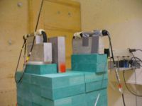
| + | The left figure above shows a close up view of the first Aluminum course collimator, followed by a wide (blue) scintillator, then an Aluminum brick with a 3 mm diameter hole, followed by the Drift chamber known as Plastica, then Metallica. Both detectors are sitting on a translation table capable of moving both horizontally and vertically. The right figure shows a wider view of the apparatus. Another scintillator paddle was placed downstream of the drift chambers. An efficiency measurement is facilitated using a coincidence formed between the first two scintillators which sandwhich the drift chambers. An alignment laser is visible at the most downstream location visible in the photo. | ||
| − | |||
| − | + | We had an Aluminum brick with three different diameter (1, 3, and 6 mm) holes. | |
We put an aluminum brick in front of the electron beam in order to look at photons hitting the Drift Chamber. | We put an aluminum brick in front of the electron beam in order to look at photons hitting the Drift Chamber. | ||
We saw a signal out of the drift chamber once for every 10 gun pulses. | We saw a signal out of the drift chamber once for every 10 gun pulses. | ||
| + | |||
| + | ==Alignment == | ||
| + | |||
| + | A laser was mounted on the most downstream wall of the experimental cell and used to align the drift chambers with the beam. The laser was centered on the beam line located in the experimental hall and then the aluminum brick collimators were added in order to optimize laser transmission upstream to the beam pip blank off. The image shown in the figure below shows how the drift chambers were moved until the three sense wires ( #3,#4, and #5) reflected the laser light. The drift chambers were also tilted such that the sense wires would be horizontal with respect to the beam line. | ||
| + | |||
| + | [[Image:DC_LaserAlignment_1-4-08.jpg | 200 px]] | ||
| + | [[Image:DC_tilt_1-4-08.jpg | 200 px]] | ||
| + | |||
| + | |||
| + | == Gamma Veto== | ||
| + | |||
| + | A gamma veto scintillator was installed on the last day of the run in order to reject events that were due to brem and other gammas generated. An aluminum brick was placed after the second scintillator in order to stop the 10 MeV electrons. High energy gammas however would be able to penetrate the brick. The would allow us to reject high energy gammas which created signals in our scintillators. | ||
| + | |||
| + | |||
| + | [[Image:Gamma_Veto_1-4-08.jpg | 200 px]] | ||
[[Image:Gun-Metalica_PostAmp_1-4-08_A.jpg | 200 px]] | [[Image:Gun-Metalica_PostAmp_1-4-08_A.jpg | 200 px]] | ||
Latest revision as of 16:45, 18 February 2008
Today we installed the drift chambers and had our first beam on target.
DC HV and Gas
90/10 ArCo2
| HV settings | ||
| Wire | Volts | current (A) |
| Sense | 1500 | |
| Field | -750 | |
| Guard | 750 | |
Apparatus
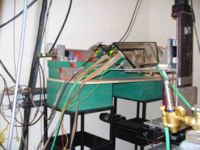
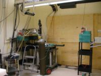
The left figure above shows a close up view of the first Aluminum course collimator, followed by a wide (blue) scintillator, then an Aluminum brick with a 3 mm diameter hole, followed by the Drift chamber known as Plastica, then Metallica. Both detectors are sitting on a translation table capable of moving both horizontally and vertically. The right figure shows a wider view of the apparatus. Another scintillator paddle was placed downstream of the drift chambers. An efficiency measurement is facilitated using a coincidence formed between the first two scintillators which sandwhich the drift chambers. An alignment laser is visible at the most downstream location visible in the photo.
We had an Aluminum brick with three different diameter (1, 3, and 6 mm) holes.
We put an aluminum brick in front of the electron beam in order to look at photons hitting the Drift Chamber.
We saw a signal out of the drift chamber once for every 10 gun pulses.
Alignment
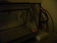
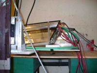
A laser was mounted on the most downstream wall of the experimental cell and used to align the drift chambers with the beam. The laser was centered on the beam line located in the experimental hall and then the aluminum brick collimators were added in order to optimize laser transmission upstream to the beam pip blank off. The image shown in the figure below shows how the drift chambers were moved until the three sense wires ( #3,#4, and #5) reflected the laser light. The drift chambers were also tilted such that the sense wires would be horizontal with respect to the beam line.
Gamma Veto
A gamma veto scintillator was installed on the last day of the run in order to reject events that were due to brem and other gammas generated. An aluminum brick was placed after the second scintillator in order to stop the 10 MeV electrons. High energy gammas however would be able to penetrate the brick. The would allow us to reject high energy gammas which created signals in our scintillators.
