HRRL radiation tests
Building a new positron beamline in the HRRL cell might require moving the linac itself. R adiation levels were measured on Feb 4, 2009 by M. Balzer and G. Stancari to determine the impact of repositioning the HRRL RF cavity in the accelerator room.
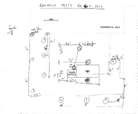
The HRRL was used to accelerate electrons to a 15 MeV beam energy, 20 mA peak current, 1 kHz repetition rate, and 30 ns pulse width. Five OSL dosimeters (For Details on OSL dosimeter, look [[1]]) were placed at each of 15 locations within the cell identified in the sketch below.
Media:dosimeter-locations-20090204.pdf
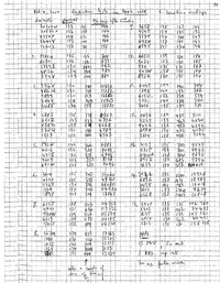
Readings in mrad are reported in the following table. They were taken before exposure (first column) and after a couple of minutes of machine tuning (second column). Readings in the third column were taken 94 minutes after the second reading. During these 94 minutes, the machine was running with the settings mentioned above.
Media:exposure-measurements-20090204.pdf
Dose rates in mrad/hr at each of the 15 locations can be estimated by subtracting column 2 from column 3, averaging over the 5 dosimeters, and multiplying the result by (60 min/hr) / (94 min). RMS spreads refer to variations within each group of 5.
| Location | Dose rate | RMS spread |
|---|---|---|
| (mrad/hr) | (mrad/hr) | |
| 1 | 9 | 4 |
| 2 | 396 | 57 |
| 3 | 7940 | 204 |
| 4 | 2831 | 117 |
| 5 | 4408 | 373 |
| 6 | 29339 | 3332 |
| 7 | 72517 | 687 |
| 8 | 36507 | 4746 |
| 9 | 5 | 5 |
| 10 | 37 | 4 |
| 11 | 164 | 40 |
| 12 | 2734 | 313 |
| 13 | 5828 | 120 |
| 14 | 7793 | 2579 |
| 15 | 62431 | 27155 |
OSL dosimeters
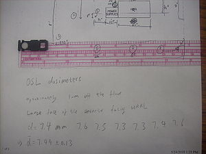
Dosimeters are placed approximately 1-m off the floor. Large face of the dosimeters were facing HRRL.
Diameter of a dosimeter is measured as:
d = 7.4 mm, 7.6 mm, 7.5 mm, 7.3 mm, 7.3 mm, 7.4 mm, 7.6 mm.
so,
d = 7.44 0.13 mm.
Experimental Cell Dose Measurement with HRRL
This experiment is done on 5/17/2010, at 10:00 am.
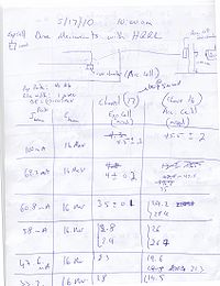
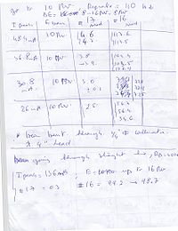
Dr. Khalid Chouffani wrote the note. Here is photocopy of his note:
page #1
page #2
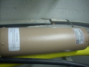
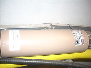
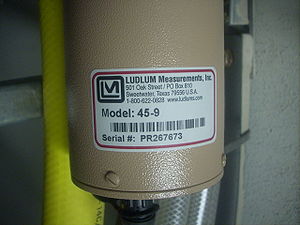
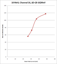
Detector Used on Channel 16
Link to detector information from producer: [2]
For more detailed information go to: ludlums_Gamma_Area_Monitor_moedl_45-9
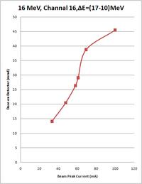
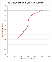
16 MeV Beam Energy
Experimental cell measurement with HRRL.
Conditions are:
Rep rate: 40 Hz
Pulse width: 1
E=(10-17) MeV
| Peak current of beam (mA) | Energy of beam (MeV) | Measurement on Channel 17, Experimental Cell (mrad) | Measurement on Channel 16, Accelerator cell (mrad) |
| 100 | 16 | 4.5 0.2 | 45.5 2 |
| 69.2 | 16 | 4 0.2 | 35, 42.5 |
| 60.8 | 16 | 3.5 0.1 | 29.2, 28.9 |
| 58.0 | 16 | 2.8, 2.9 | 26, 26.7 |
| 47.6 | 16 | 2.3 | 19.6, 21.3 |
| 33.2 | 16 | 1.8, 1.7 | 19.5, 19.0, 13.7 |
Beam bear through 1/4 inches diameter collimator with 4 inches lead.
16 MeV Beam Energy
Conditions are:
Rep rate: 40 Hz
| Peak current of beam (mA) | Energy of beam (MeV) | Measurement on Channel 17, Experimental Cell (mrad) | Measurement on Channel 16, Accelerator cell (mrad) |
| 136 | 16 | 0.3 | 99.2, 98.7 |
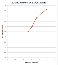
10 MeV Beam Energy
Conditions are:
Rep rate: 110 Hz
E=(8-16) MeV
| Peak current of beam (mA) | Energy of beam (MeV) | Measurement on Channel 17, Experimental Cell (mrad) | Measurement on Channel 16, Accelerator cell (mrad) |
| 48.4 | 10 | 4.6, 4.7 | 117.6, 117.5 |
| 36.8 | 10 | 3.8, 3.9 | 104.4, 103.5, 102.9 |
| 30.8 | 10 | 3.1 0.1 | 72.8, 72.9, 72.5 |
| 26 | 10 | 2.5 | 56.7, 56.4, 54.6 |
Fit for channel 17
| Order of the fit | Fit equations | Chi square | p-value |
| 1st order | 24.91 | 0.000004 |
Fit for channel 16
| Order of the fit | Fit equations | Chi square | p-value |
| 1st order | 437.5 | less than 0.0001 |
Channel 17 Dose Estimation in New Position
Channel 17 is a dose measuring detector on in the HRRL experimental cell.
Calculating Number of Incident Electrons Per Second
We have electron beam of:
Frequency: f (Hz)
Peak current: I (mAmp = 0.001 Amp)
Pulse width: t ( seconds )
So, how many electrons we have in each second?
By Q=It, we have
Where N is the total electron numbers hits target per second, e is electron charge and f, I and are given above. So
Number of Particles Per Second in test by M. Balzer on Feb 4, 2009
In radiation levels measured on Feb 4, 2009 by M. Balzer and G. Stancari
Five OSL dosimeters were placed at each of 15 locations in the cell. (What is OSL? Need to ask M. Balzer)
The HRRL was set at 15 MeV beam energy, 20 mA peak current, 1 kHz repetition rate, and 30 ns pulse width.
Number of Particles Per Second in "Experimental Cell Dose Measurement with HRRL" on 5/17/201
This is the experiment we have done on 5/17/201 to measure dose on the detector placed in the corner of the doorway.
Conditions are: Pulse width: 1 , Rap rate: 110 Hz.
We measured dose for several peak current. One of the peak current is 26 mA. For this peak current:
Calculation
Assume that the position 13 at radiation test on Feb 4, 2009 by M. Balzer and G. Stancari will shift to detector position at corner on experiment that is done on 5/17/2010.
Radiation test on Feb 4, 2009 by M. Balzer and G. Stancari used OSL dosimeter.
The area of a OSL dosimeter is:
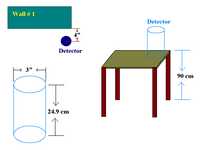
Experimental Cell Dose Measurement with HRRL on 5/17/2010 used Ludlums Gamma Area Monitor moedl 45-9 for channel 16. Ludlums Gamma Area Monitor moedl 45-9 has dimension: 7.6 x 25.7 cm (3 x 10.1 in.) (Dia x L).
The area of a Ludlums Gamma Area Monitor moedl 45-9 is:
The ratio of detectors detecting area is:
We assume 100% efficiency for both detectors, their detecting are ratio is their dose ratio.
So, for 15 MeV electron beam, at the corner where we had detector of channel 16, if we moved detector to new position, on the detector of Ludlums Gamma Area Monitor moedl 45-9 we would have dose rate of :
Dose
This dose is created by electron beam of energy 15 MeV and .
Also assume same dose rate for 16 MeV and 15 MeV electron beam energy.
Back to Positrons
