Difference between revisions of "HRRL Positrons Jul 2012 Runs Setup"
(→Wiring) |
|||
| Line 131: | Line 131: | ||
NaI dynode --> 474 Timing Amp (x20). (Dynode signal is weak.) | NaI dynode --> 474 Timing Amp (x20). (Dynode signal is weak.) | ||
| + | |||
| + | [[File:hrrl_pos_jul2012_setup_wiring_1.jpg | 300 px]] | ||
Timing Amp --> 8CH CFD (CAEN Mod. N842). (DL-THR = 31, DR-THR = 52.) | Timing Amp --> 8CH CFD (CAEN Mod. N842). (DL-THR = 31, DR-THR = 52.) | ||
| Line 153: | Line 155: | ||
But when there is a coincidence between, 2 NaI detectors, fast clear is "VETO"ed. Then | But when there is a coincidence between, 2 NaI detectors, fast clear is "VETO"ed. Then | ||
data was saved and the trigger comes 6 micro-second after the gate, then data is saved. | data was saved and the trigger comes 6 micro-second after the gate, then data is saved. | ||
| − | |||
=DAQ Setup= | =DAQ Setup= | ||
Pulse from the gun is always generating a gate. When there is a gate DAQ reads data. But the data is fast cleared, unless there is veto. veto is generated by the coincidence from the 2 NaI detector dynode signals. Dynode signals from 2 NaI detectors are discriminated with CFD, and cleared from RF noise (by forming a pulse to veto using RF trigger pulse), then sent to form coincidence. The coincidence formed with logic of (DL & GunTrig) & (DR & GunTrig), that is (detector left AND gun trigger) AND (detector right AND gun trigger). | Pulse from the gun is always generating a gate. When there is a gate DAQ reads data. But the data is fast cleared, unless there is veto. veto is generated by the coincidence from the 2 NaI detector dynode signals. Dynode signals from 2 NaI detectors are discriminated with CFD, and cleared from RF noise (by forming a pulse to veto using RF trigger pulse), then sent to form coincidence. The coincidence formed with logic of (DL & GunTrig) & (DR & GunTrig), that is (detector left AND gun trigger) AND (detector right AND gun trigger). | ||
Revision as of 22:28, 31 July 2012
Targets
2 targets are from MIDWEST TUNGSTEN SERVICE.
0.040" x 1.50" x1.50". 99.95% Tungsten foils with four holes.
0.04" = 1.016 mm .
Materiel certification
Fe   0.0011%
Al   0.0010%
Ni   0.0010%
Si   0.0010%
C    0.0010%
N2   0.0020%
O2   0.0070%
W 99.95% minimum.
File:CHIPs T1 TungstenTargetMatCert 0.8mm.pdf
T1 is placed with a vertical angle of 45 degree with respect to the beamline.
T2 is placed with vertical and horizantal angles of 45 degree with respect to the beamline.
Switching T2
T2 was switched from 2 mm target to 1 mm target [Switching Target].
T2 is facing Detector Right
T2 is facing Detector Right.
May be that is why detector right has less noise in its spectrum than detector left.
Because to make it to detector left, photons goes through thicker tungsten.
Detectors setup
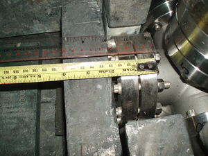
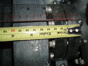
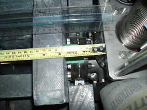
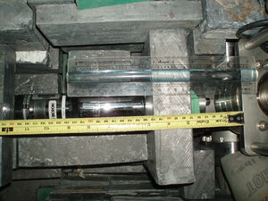
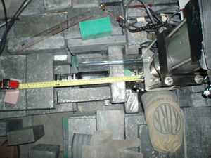
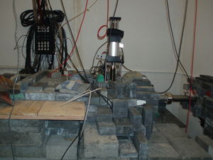
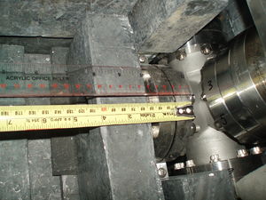
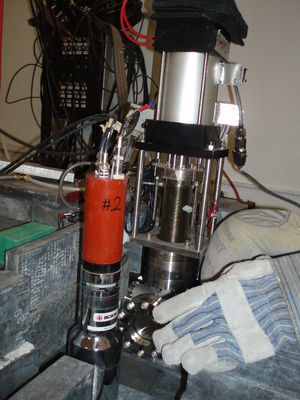
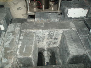
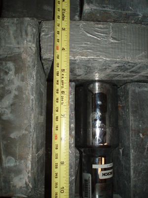
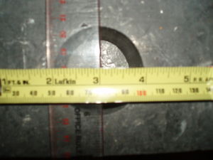
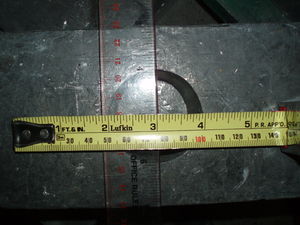
2" thick brick with 2" diameter hole placed at the exit of the vacuum window, then NaI detectors were placed next to the brick. The distance between NaI detector and the edge of the 6-way cross is
Detector Left:
Detector Right:
Collimator Pb Brick
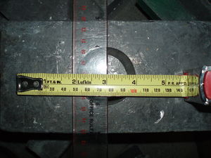
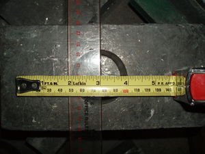
There is 2" thick Pb brick with 2" diameter hole to act as collimator.
ADC inputs
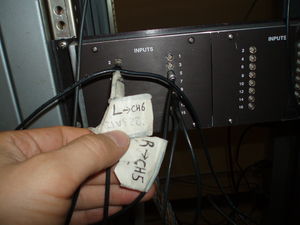
Detector Left -> CH6
Detector Right -> CH5
Beam left Scintillator (between Q9 and Q10)-> CH9
Scintillator 1 (right next to the beam exit at the the 90 deg) -> CH2.
Battery -> CH13.
Note: There were some changes going on during the experiment. The above setup was according to the sent up on 27th of Jul. All the changes were recorded.
TDC input
According to the setup on 27th:
CH0->start from the gun.
CH1->95 ns delay of the start from gun (PS model 792, DUAL Delay moduale).
CH5->Detector Right.
CH6->Detector Left.
13->Gate for signal (generated whenever there is a electron gun pulse, then fast cleared if there is no coincidence).
CH9-> discriminated output of NaI Left.
CH10-> discriminated output of NaI Right.
Scaler
The gun pulse connected to CH1 of the scaler . I thought I put it to CH0, may be somebody changed it.
HV power supply
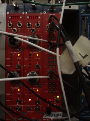
We used 2CAEN Mod. N471 power supply. There are 2 of them. 2 for NaI and one for Scintilator1.
Power supply left, top channel-> NaI left
Power supply left, bottom channel-> NaI right
Power supply right, top channel-> Scintillator 1
Power supply on the Scintillator left and right was in HRRL cell. The voltage on them were 500 V.
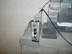
Wiring
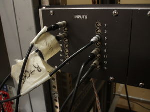
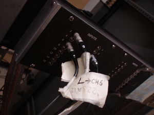
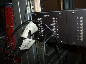
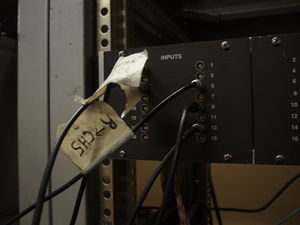
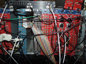
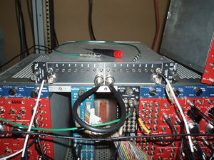
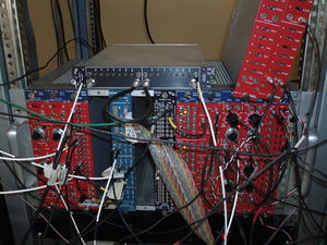
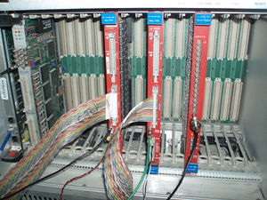
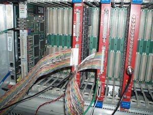
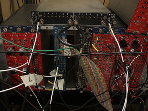
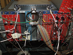
NaI dynode --> 474 Timing Amp (x20). (Dynode signal is weak.)
Timing Amp --> 8CH CFD (CAEN Mod. N842). (DL-THR = 31, DR-THR = 52.)
8CH CFD --> Octal Discriminator (PS model 710). (To use its veto to get rid off RF noise.)
Octal Dis --> Octalgate Generator (GG 8000-01). (To combine multi-pulses to a single wide pulse.)
Octalgate  -->  Quad coincidence (LeCroy model 622). (To generate AND logic between Gun and signal.)
                Logic is set as: (DL && GunTrig) && (DR && GunTrig) or (DL AND GunTrig) AND (DR AND GunTrig).
Quad Coin --> Octalgate Generator (GG 8000-01). (To get better pulse.)
Octalgate 1 --> ORTEC Gate & Delay Generator (416-06). (To create 6 micro-second delayed (from signal Gate) trigger )
Gate-Delay --> SIS GmbH CH1. (Trigger for DAQ.)
Octalgate 2  --> DUAL timer ( CAEN Mod. N93B, at right side). (To do VETO for Gate).
                 Whenever there is a gun pulse, a gate generated and date taken. Then data is fast cleared.
                 But when there is a coincidence between, 2 NaI detectors, fast clear is "VETO"ed. Then
                 data was saved and the trigger comes 6 micro-second after the gate, then data is saved.
DAQ Setup
Pulse from the gun is always generating a gate. When there is a gate DAQ reads data. But the data is fast cleared, unless there is veto. veto is generated by the coincidence from the 2 NaI detector dynode signals. Dynode signals from 2 NaI detectors are discriminated with CFD, and cleared from RF noise (by forming a pulse to veto using RF trigger pulse), then sent to form coincidence. The coincidence formed with logic of (DL & GunTrig) & (DR & GunTrig), that is (detector left AND gun trigger) AND (detector right AND gun trigger).
