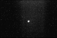
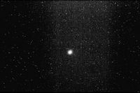
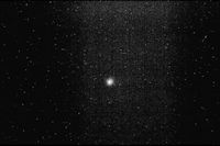
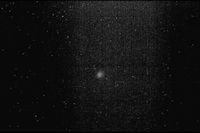
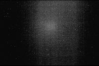
HRRL OTR Test Feb 16th 2011

From New IAC Wiki
Revision as of 06:28, 21 April 2012 by Setisadi (talk | contribs) (→‎Average current)
(diff) ← Older revision | Latest revision (diff) | Newer revision → (diff)
Jump to navigation Jump to search

Objectives

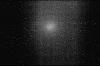
1.) Check alignment of the OTR target and beam line with the linac's central axis. If it is misaligned we will work on an alignment plan to be executed after the Wednesday beam test.

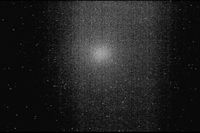
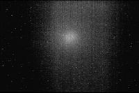
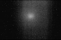
2.) Take OTR images, check image focus and light output.

3.) Determine which quad to use for emittance measurements. Establish a quad current scan range.

Steps

Practise Turning HRRL On

Make document of the whole process, write a Standard Operation Process (SOP).

Turn RF off, Try to see Image with filament on

If we can see filament spot on the OTR target, try to focus our image system.

Turn RF On

Turn RF on look at the images, take pictures of the image upload them to the wiki.


Experiment

First Fusing

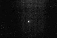
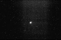
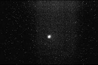
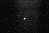
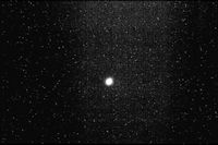
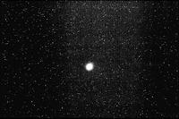
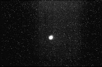
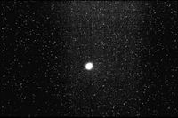
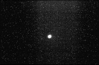
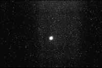
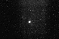
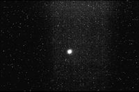
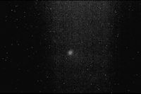
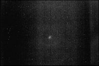
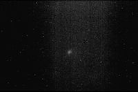
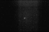
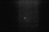
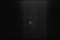
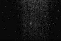
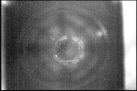
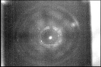
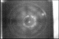
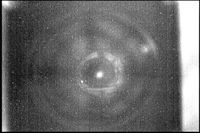
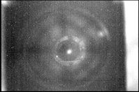
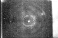
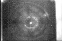
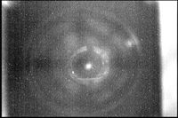
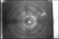
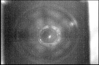
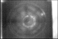
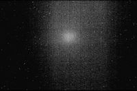
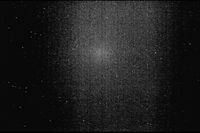
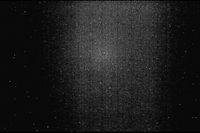
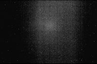
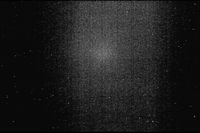
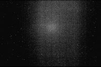
Image on OTR target

Lights RF image
on off HRRL Emit Lens Sys Feb 16th 2011 Run 1.jpg
on (different contrast) off HRRL Emit Lens Sys Feb 16th 2011 Run 2.jpg
off off HRRL Emit Lens Sys Feb 16th 2011 Run 3.jpg
on on (27 Hz) HRRL Emit Lens Sys Feb 16th 2011 Run 5.jpg

RF:25-205, Peak Current50mA, Pulse Width_200ns (fwhm)

HRRL Emit Lens Sys Feb 16th 2011 Run RF25-205 Current 50mApeak PulseWidth 200ns fwhm 1.jpg HRRL Emit Lens Sys Feb 16th 2011 Run RF25-205 Current 50mApeak PulseWidth 200ns fwhm 2.jpg HRRL Emit Lens Sys Feb 16th 2011 Run RF25-205 Current 50mApeak PulseWidth 200ns fwhm 3.jpg HRRL Emit Lens Sys Feb 16th 2011 Run RF25-205 Current 50mApeak PulseWidth 200ns fwhm 4.jpg HRRL Emit Lens Sys Feb 16th 2011 Run RF25-205 Current 50mApeak PulseWidth 200ns fwhm 5.jpg HRRL Emit Lens Sys Feb 16th 2011 Run RF25-205 Current 50mApeak PulseWidth 200ns fwhm 6.jpg HRRL Emit Lens Sys Feb 16th 2011 Run RF25-205 Current 50mApeak PulseWidth 200ns fwhm 7.jpg HRRL Emit Lens Sys Feb 16th 2011 Run RF25-205 Current 50mApeak PulseWidth 200ns fwhm 8.jpg HRRL Emit Lens Sys Feb 16th 2011 Run RF25-205 Current 50mApeak PulseWidth 200ns fwhm 9.jpg HRRL Emit Lens Sys Feb 16th 2011 Run RF25-205 Current 50mApeak PulseWidth 200ns fwhm 10.jpg HRRL Emit Lens Sys Feb 16th 2011 Run RF25-205 Current 50mApeak PulseWidth 200ns fwhm 11.jpg HRRL Emit Lens Sys Feb 16th 2011 Run RF25-205 Current 50mApeak PulseWidth 200ns fwhm 12.jpg HRRL Emit Lens Sys Feb 16th 2011 Run RF25-205 Current 50mApeak PulseWidth 200ns fwhm 13.jpg HRRL Emit Lens Sys Feb 16th 2011 Run RF25-205 Current 50mApeak PulseWidth 200ns fwhm 14.jpg HRRL Emit Lens Sys Feb 16th 2011 Run RF25-205 Current 50mApeak PulseWidth 200ns fwhm 15.jpg HRRL Emit Lens Sys Feb 16th 2011 Run RF25-205 Current 50mApeak PulseWidth 200ns fwhm 16.jpg HRRL Emit Lens Sys Feb 16th 2011 Run RF25-205 Current 50mApeak PulseWidth 200ns fwhm 17.jpg HRRL Emit Lens Sys Feb 16th 2011 Run RF25-205 Current 50mApeak PulseWidth 200ns fwhm 18.jpg

RF:25, Peak Current60mA, Pulse Width_200ns (fwhm)

HRRL Emit Lens Sys Feb 16th 2011 Run RF25 Current 60mApeak PulseWidth 200ns fwhm 1.jpg HRRL Emit Lens Sys Feb 16th 2011 Run RF25 Current 60mApeak PulseWidth 200ns fwhm 2.jpg HRRL Emit Lens Sys Feb 16th 2011 Run RF25 Current 60mApeak PulseWidth 200ns fwhm 3.jpg HRRL Emit Lens Sys Feb 16th 2011 Run RF25 Current 60mApeak PulseWidth 200ns fwhm 4.jpg HRRL Emit Lens Sys Feb 16th 2011 Run RF25 Current 60mApeak PulseWidth 200ns fwhm 5.jpg HRRL Emit Lens Sys Feb 16th 2011 Run RF25 Current 60mApeak PulseWidth 200ns fwhm 6.jpg


RF:50

Light is on

HRRL Emit Lens Sys Feb 16th 2011 Run RF50 1.jpg HRRL Emit Lens Sys Feb 16th 2011 Run RF50 2.jpg HRRL Emit Lens Sys Feb 16th 2011 Run RF50 3.jpg HRRL Emit Lens Sys Feb 16th 2011 Run RF50 4.jpg HRRL Emit Lens Sys Feb 16th 2011 Run RF50 5.jpg HRRL Emit Lens Sys Feb 16th 2011 Run RF50 6.jpg HRRL Emit Lens Sys Feb 16th 2011 Run RF50 7.jpg HRRL Emit Lens Sys Feb 16th 2011 Run RF50 8.jpg HRRL Emit Lens Sys Feb 16th 2011 Run RF50 9.jpg HRRL Emit Lens Sys Feb 16th 2011 Run RF50 10.jpg HRRL Emit Lens Sys Feb 16th 2011 Run RF50 11.jpg

Second Fusing

Focused With Lenses,140 mA 58Hz 100ns

HRRL Emit Lens Sys Feb 16th 2011 Run 2ndFocus RF58 Current 140mApeak PulseWidth 100ns fwhm 1.jpg HRRL Emit Lens Sys Feb 16th 2011 Run 2ndFocus RF58 Current 140mApeak PulseWidth 100ns fwhm 2.jpg HRRL Emit Lens Sys Feb 16th 2011 Run 2ndFocus RF58 Current 140mApeak PulseWidth 100ns fwhm 3.jpg HRRL Emit Lens Sys Feb 16th 2011 Run 2ndFocus RF58 Current 140mApeak PulseWidth 100ns fwhm 4.jpg HRRL Emit Lens Sys Feb 16th 2011 Run 2ndFocus RF58 Current 140mApeak PulseWidth 100ns fwhm 5.jpg HRRL Emit Lens Sys Feb 16th 2011 Run 2ndFocus RF58 Current 140mApeak PulseWidth 100ns fwhm 6.jpg HRRL Emit Lens Sys Feb 16th 2011 Run 2ndFocus RF58 Current 140mApeak PulseWidth 100ns fwhm 7.jpg HRRL Emit Lens Sys Feb 16th 2011 Run 2ndFocus RF58 Current 140mApeak PulseWidth 100ns fwhm 8.jpg HRRL Emit Lens Sys Feb 16th 2011 Run 2ndFocus RF58 Current 140mApeak PulseWidth 100ns fwhm 9.jpg HRRL Emit Lens Sys Feb 16th 2011 Run 2ndFocus RF58 Current 140mApeak PulseWidth 100ns fwhm 10.jpg HRRL Emit Lens Sys Feb 16th 2011 Run 2ndFocus RF58 Current 140mApeak PulseWidth 100ns fwhm 11.jpg


Determine the smallest energy, beam current, pulse width, and rep rate for a visible image.


Visible Image for Lowest Parameters

First Focus

Second Focus

Following images are taken under conditions that: 100 ns FWHM pulse width, 25 Hz Repetition Rate:
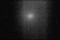
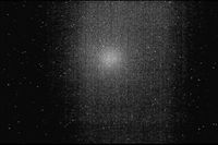
Beam off HRRL Emit Lens Sys Feb 16th 2011 Run Visible Image for Lowest Parameters 2ndFocus 30mA Peak Current 25Hz RF 100ns FWHM PulseWidth beamOff.jpg
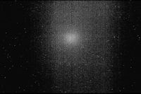
 20 mA peak current image is the lowest noticeable under 100 ns FWHM pulse width, 25 Hz repetition rate.

20 mA Peak Current HRRL Emit Lens Sys Feb 16th 2011 Run Visible Image for Lowest Parameters 2ndFocus 20mA Peak Current 25Hz RF 100ns FWHM PulseWidth beamOn.jpg

30 mA Peak Current HRRL Emit Lens Sys Feb 16th 2011 Run Visible Image for Lowest Parameters 2ndFocus 30mA Peak Current 25Hz RF 100ns FWHM PulseWidth beamOn.jpg

50 mA Peak Current HRRL Emit Lens Sys Feb 16th 2011 Run Visible Image for Lowest Parameters 2ndFocus 50mA Peak Current 25Hz RF 100ns FWHM PulseWidth beamOn.jpg

60 mA Peak Current HRRL Emit Lens Sys Feb 16th 2011 Run Visible Image for Lowest Parameters 2ndFocus 60mA Peak Current 25Hz RF 100ns FWHM PulseWidth beamOn.jpg

70 mA Peak Current HRRL Emit Lens Sys Feb 16th 2011 Run Visible Image for Lowest Parameters 2ndFocus 70mA Peak Current 25Hz RF 100ns FWHM PulseWidth beamOn.jpg

80 mA Peak Current HRRL Emit Lens Sys Feb 16th 2011 Run Visible Image for Lowest Parameters 2ndFocus 80mA Peak Current 25Hz RF 100ns FWHM PulseWidth beamOn.jpg

90 mA Peak Current HRRL Emit Lens Sys Feb 16th 2011 Run Visible Image for Lowest Parameters 2ndFocus 90mA Peak Current 25Hz RF 100ns FWHM PulseWidth beamOn.jpg

100 mA Peak Current HRRL Emit Lens Sys Feb 16th 2011 Run Visible Image for Lowest Parameters 2ndFocus 100mA Peak Current 25Hz RF 100ns FWHM PulseWidth beamOn.jpg

110 mA Peak Current HRRL Emit Lens Sys Feb 16th 2011 Run Visible Image for Lowest Parameters 2ndFocus 110mA Peak Current 25Hz RF 100ns FWHM PulseWidth beamOn.jpg

120 mA Peak Current HRRL Emit Lens Sys Feb 16th 2011 Run Visible Image for Lowest Parameters 2ndFocus 120mA Peak Current 25Hz RF 100ns FWHM PulseWidth beamOn.jpg

140 mA Peak Current HRRL Emit Lens Sys Feb 16th 2011 Run Visible Image for Lowest Parameters 2ndFocus 140mA Peak Current 25Hz RF 100ns FWHM PulseWidth beamOn.jpg


Estimation of Single Bunch Charge

S-band linac has RF frequency of 2856 MHz. The period then is:

[math]T_{RF}=\frac{1}{f_{RF}}=\frac{1}{2856MHz}=350~ps[/math]

Pulse width of the RF macro-pulse : [math]\Delta t[/math].

Number of bunches within a pulse: [math]N[/math]

[math]N \times T_{RF} = \Delta t[/math]

[math]N=\frac{\Delta t}{T_{RF}}[/math]


Peak current of the pulse: [math]I_{peak}[/math]

Total Charge in a macro pulse: [math]Q_t=I_{peak} \times \Delta t [/math]

Charge in a single bunch: [math]Q_{s} = \frac{Q_t}{N} [/math]

[math]Q_{s} = \frac{ I_{peak} \times \Delta t }{ \frac{\Delta t}{T_{RF}} } [/math]

[math]Q_{s} = { I_{peak} \times }T_{RF} [/math]

[math]Q_{s} = { I_{peak} \times }350~ps [/math]


I_{peak} (mA) Q_{s} (pC)
10 mA 3.5
20 mA 7
30 mA 10.5
40 mA 14
50 mA 17.5
60 mA 21
70 mA 24.5
80 mA 28
90 mA 31.5
100 mA 35
110 mA 38.5
120 mA 42
130 mA 45.5
140 mA 49


Average current

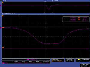
Scope image of good Accelarator setting by Dr. Kim Mar 17 2011.png

Area under the curve: A = 315.6 nsV.

Macro pulse [math]\Delta t[/math] = 200 ns.

Average Voltage: [math]V_{ave} = A / \Delta t[/math] = 315.6 nsV / 200 ns.

Scope impedance: R = 50 [math]\Omega [/math]

Average Current: [math]I_{ave} = V_{ave}/R = \frac{315.6 nsV } {200 \times 50~\Omega ns} = 31.56~mA[/math].


[math]Q_{s} = { I_{ave} \times }T_{RF} [/math]

[math]Q_{s} = { I_{ave} \times }350~ps [/math]


[math]Q_{s} = { 31.56~mA \times }350~ps = 11.046~pC[/math]


Back to Positrons