Difference between revisions of "G4Beamline PbBi"
| Line 90: | Line 90: | ||
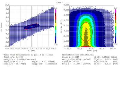
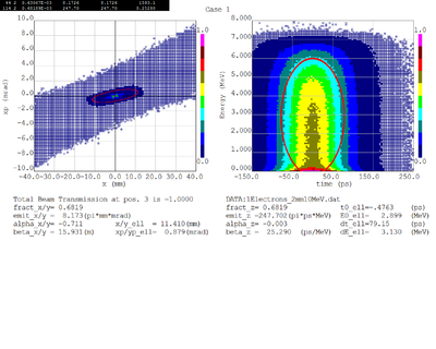
Electrons: | Electrons: | ||
| − | [[File: | + | [[File:e01.png| 200 px]][[File:e02.png| 200 px]] |
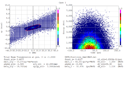
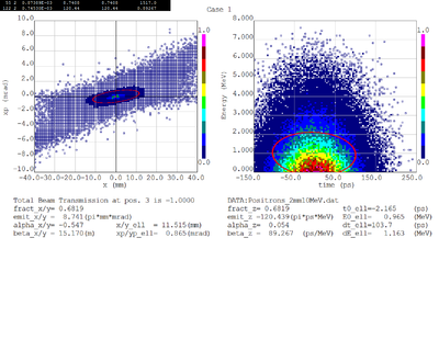
Positrons: | Positrons: | ||
| − | [[File: | + | [[File:p01.png| 200 px]][[File:p02.png| 200 px]] |
===Energy Deposition in Target system (Heat)=== | ===Energy Deposition in Target system (Heat)=== | ||
Revision as of 21:02, 21 May 2015
Development of a Positron source using a PbBi converter and a Solenoid
Converter target properties
Definition of Lead Bismuth
1cm diameter target
2 mm thick PbBi
0.5 Tesla solenoid
Desire to know
Emmittance (mrad * mm)
dispersion (Delta P/P) (mradian/1000th mm/1000th)
of electrons after the PbBi target.
pole face rotation in vertical plane.
G4BeamLine and MCNPX
Target thickness optimization
PbBi_THickness_GaussBeam
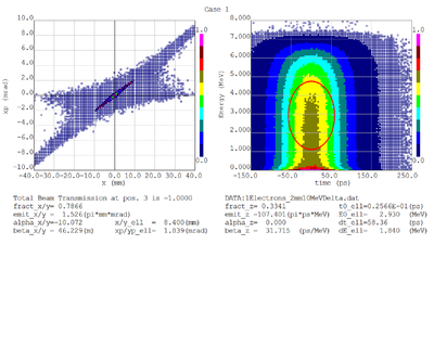
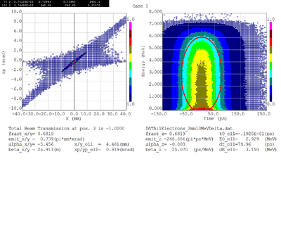
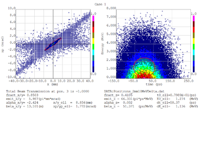
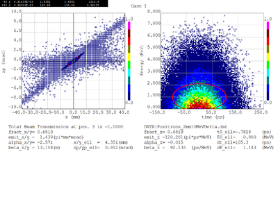
Dmitry's processing of Tony's GEANT simulations showing transverse phase space portrait (left) and longitudinal phase space portrait (right). Phase space portraits show coordinate x or y vs diveregense=px/pz or py/pz (or time vs kinetic energy ). Captions show:
1. geometric (not normalized) emittance for transverse and emittance for longitudinal phase space portraits (ellipse areas divided by "pi")
2. Twiss parameters
3. Ellipse centroid for longitudinal phase portrait
4. sqrt(beta*emittance) and sqrt(gamma*emittance) - half sizes of the projections of the ellipses on the coordinate and divergence axes respectively.
Electrons - RMS
Electrons - 68.2% core
Positrons - RMS
Positrons - 68.2% core
PbBi_THickness_CylinderBeam
Dmitry's processing of Tony's GEANT simulations showing transverse phase space portrait (left) and longitudinal phase space portrait (right). Phase space portraits show coordinate x or y vs diveregense=px/pz or py/pz (or time vs kinetic energy ). Captions show:
1. geometric (not normalized) emittance for transverse and emittance for longitudinal phase space portraits (ellipse areas divided by "pi")
2. Twiss parameters
3. Ellipse centroid for longitudinal phase portrait
4. sqrt(beta*emittance) and sqrt(gamma*emittance) - half sizes of the projections of the ellipses on the coordinate and divergence axes respectively.
Electrons - RMS
Electrons - 68.2% core
Positrons - RMS
Positrons - 68.2% core
PbBi_THickness_PntSource
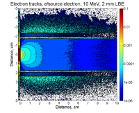
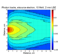
Electrons and Positrons after 2mm of LBE:
Electrons:
Positrons:
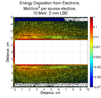
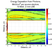
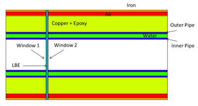
Energy Deposition in Target system (Heat)
MCNPX simulations of energy deposition into different cells are below. There is a slight overestimate (they add up to about 120%). Positrons contribute less than 1% of electrons' contribution. No magnetic filed is assumed.
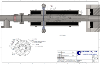
Solenoid
Inner Radiusu=
Outer Radius =
Length =
Current=
Magnetic Field Map in cylindrical coordinates (Z & R) from Niowave
