Forest RC circuits
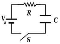
The circuit diagram below defines a common circuit known as an RC circuit. The circuit involves only a capacitor and a resistor. The resistors role is to impede (resist) the flow of current (iR) and the capacitors role is to store charge (q/C).
Pumping air into a bicycle tire is a fair analogy of this circuits properties. You are the battery, the pump you push is the resistor and the tire is the capacitor. As a battery you push electrons through the resistor (pump) and into the capacitor. The resistor (pump) resists the flow of the electrons into the capacitor. As the capacitor starts to charge up (tire fills with air) it becomes harder to push electrons onto the capacitors plates (add air to the tire). Now the capacitor (tire) starts to resist you pumping making it harder to charge up.
Discharging RC circuit
Let's first describe what happens when a fully charged capacitor is allowed to discharge (You pumped up your bike tire but you forgot to put the stem in the valve and all the air starts leaking out when you take off the pump). Assume we left the battery connected to the above circuit for an infinite amount of time.
If we apply Kirchhoff's loop Theorem by starting at the location of the battery and go around clockwise we would write
If we then replaced the batteries EMF with a wire so it was no longer working to keep the charge on the capacitor. Then we would have the equation
Another way to arrive at the equation above is to think of the capacitor as being a charged up battery with a voltage of which is discharging with a current.
Then you would have
The above is a first order differential equation which you can integrate directly
- Quiz
- Integrate the above differential equation for a discharging capacitor to determine the dependence of charge (q) with time (t). Which of the answers below looks most like yours.
A.) B.) C.) D.)
- Answer
Assume the capacitor has been charged up to a total charge Q
Charging RC circuit
Let's now assume we waited an infinite amount of time for the capacitor to discharge and we are interested in the charge as a function of time on the capacitor when we turn the battery back on.
- Kirchhoff's Loop theorem with the battery inserted says
or
the above differential equation is similar to the equation for a discharging capacitor except that instead of zero on the RHS we have the battery's voltage . This is called a 1st order differential equation with a source term.
Diff. Eq. sol. method #1
A common and more general technique to solving such a differential equation is to use the solution from the discharging equation (the homogeneous diff. eq.) as a trial solution by inserting constants.
You then substitute this trial solution into the differential equation and apply boundary conditions to determine the coefficients.
To determine the other coefficient you apply the boundary condition that q = 0 when t=0
- Note
- you can also show that if you apply the boundary condition that when .
Diff. Eq. sol. method #2
An important feature of our differential equation for the charging capacitor is that the right hand side is a constant with time (perfect battery). If we differentiate with respect to time we get an equation that is analogous to the differential equation for a discharging capacitor.
or
the differential equation for the charge(q) in a discharging capacitor is the same as the differential equation for the current I in a charging capacitor.
- just copy the solution for a discharging capacitor and replace "q" with "I"
where is the current from the battery when the battery has just been turned on.
- Note
- as the capacitor charges up the current drawn from the battery will be less because the capacitor is working against the electromotive force of the battery.
the equation
- is just a differential equation for the charge
by directly integrating we have
