Development of Compact Plasma Radiation Source (CPRS) at IAC for imaging
Introduction
- N.Ratakhin et al. "Compact pulse power generator for X-pinch researches" 28th ICPIG, July 15-20, 2007, Prague, Czech Republi [1]
"The main requirements imposed on the generator are the current amplitude 150-300 kA and the rate of the current rise 1-2 kA/ns. At the moment, these parameters of the current pulse can be provided only by enough large fixed-site generators weighing from 300 kg to several tons. These shortcomings limit to a great extent the feasibility of this diagnostic technique in studies of extreme states. Therefore, the design of a portable pulse generator which provides the required parameters makes it possible to proceed to a new level of diagnostics of fast processes."
Comparison of X-Pinch X-ray Radiography Facilities with other X-Ray sources
X-Pinch :
- few micron source size -> study small-scale objects
- 0.1 - 10 ns Pulse Width -> study short living objects
- X-Pinch Facilities used Pulsed Power and could be made small and compact
Synchrotron Radiation:
Laser Compton Scattering:
Design's Possibilities
PRS based on transformation of ISIS Induction Cell Driver
File:ISIS Modification for X-pinch 012813.pdf
PRS based on building separate Marx Generator or (Marx Generator + Pulse Forming Line)
PRS based on Linear Transformer Driver (LTD) technologies
- M.G.Mazarakis, A compact, high-voltage e-beam pulser, 1999 IEEE [2]
- M.G.Mazarakis Ultrafast LTD's for bremsstrahlung diodes and Z-pinches 2002 IEEE [3]
- A.A.Kim 1 MV ultra-fast LTD generator 2003 IEEE [4]
- M.G.Mazarakis High Current Fast 100-NS LTD Driver Development in Sandia Laboratory 2005 IEEE [5]
- M.G.Mazarakis Conceptual Design for a Linear-Transformer Driver (LTD)-Based Refurbishment and Upgrade of the Saturn Accelerator Pulse-Power System SANDIA REPORT SAND2006-5811, 2006 [6]
- M.G. Mazarakis Linear Transformer Driver (LTD) development at Sandia national laboratory 2009 IEEE [7]
- J.R.Woodworth Low-inductance gas switches for linear transformer drivers Phys. Rev. ST Accel. Beams 12, 060401 (2009) [8]
- W.A.Stygar Shaping the output pulse of a linear-transformer-driver module Phys. Rev. ST Accel. Beams 12, 030402 (2009) [9]
- A.A. Kim Development and tests of fast 1-MA linear transformer driver stages Phys. Rev. ST Accel. Beams 12, 050402 (2009) [10]
- M.G. Mazarakis High current, 0.5-MA, fast, 100-ns, linear transformer driver experiments Phys. Rev. ST Accel. Beams 12, 050401 (2009) [11]
- M.G. Mazarakis High-Current Linear Transformer Driver Development at Sandia National Laboratories 2010 IEEE [12]
- J. R. Woodworth Compact 810 kA linear transformer driver cavity Phys. Rev. ST Accel. Beams 14, 040401 (2011) [13]
"The LTD driver is an induction generator similar to the induction accelerator (LIA) [1,2], the inductive voltage adder (IVA) [3–6], and the linear pulsed transformer (LPT)" [14]
Each LTD stage (or sometimes called LTD cavities) consists of three different elements: a capacitor, a gas spark switch and a ferromagnetic core. The necessity of ferromagnetic core is to inductively connect stage to TL. So the one stage can be used as building block to design the bigger facilities. Buy designing the different stages and connecting them in different way a great variety id devices can be constructed. [15]
What was done with LTD:
- A compact, high-voltage e-beam pulser: 3 MV, 100 kA
- A compact, high-voltage e-beam pulser: 10 MV, 100 kA
- 1 MV ultra-fast LTD generator: 1 MV, 125 kA
- High Current Fast 100-NS cavity: 100 kV, 1 MA
- LTD-II: 100 kV, 490 kA
- LTD-III: 92 kV, 810 kA
- etc...
LRC circuit with Low inductance capacitors and Low Inductance Switches
For radiographic application we need the pulser with 150-300 kA current and 1-2 kA/ns rise time. Because of that, one LTD stage is enough to build the entirely facility. Because we do not need inductively stuck many stages together the necessity of massive ferromagnetic core is relaxed.
The whole stage can be easily analysed as LRC circuit with LTspice code. The precise design of cavity and transmission line should be done with 3D time domain EM code XFtdt.
Design of ISIS Compact Plasma Radiation Source (CPRS)
X-Pinch Radiography Requirements
- Compact and Light
- 150-300 kA
- 1-2 kA/ns rise time
LRC dumped circuit (R = sqrt(L/C)) [16]
- Ip = 0.546293*Vo/R
- Vp = 0.546293*Vo
- R = Ip/Vp = sqrt(L/C)
- tp = 1.2092 * sqrt(LC) = 1.2092 * L/R = 1.2092 * RC
Above:
- Ip - Load peak current
- Vp - Load peak voltage
- tp - Time of peak
LRC elements (_c - capacitors, _sw - switch) [17]
- C_c = 40 nF
- L_c = 25 nF (max)
- I_c = 25 kA max capacitor current
- V_c = 100 kV (max)
- L_sw = 10 nH
- R_load 0.05 - 10 Om
- L_load >= 15 nH
Multistep Multidimensional Optimization with several Constrains
Usually we first decide what the parameters of the generators we need, like peak current and peak voltage, and then calculate the remaining parameters, like rise time and etc.
Let say, we need the compact generator, so the number of elements m should be as small as possible. But we also want the higher peak current, smaller peak voltage and the minimum time to peak values. If so happen that we are nor satisfy with our generator parameters for given m, then we increase the m (the size and cost of generator) and look again for the best values of other parameters inside given m. And so on ans so on.
If the size of generator is not so important, the algorithm above should be different.
The general picture for multidimensional optimization with several constrains should be clear now.
- Specify all constrain of system
- Find the most important element we want to optimize.
- Start with the best possible values of the first element from above step
- Vary other elements
- Look at constrain and values of all other elements
- If we do not satisfy with parameters go to the next best values of the most important element
- etc
In general we want:
- m as small as possible (to make facility compact and cheap)
- Ip as big as possible (to increase energy deposition per ns)
- Vp as small as possible.
- to have freedom later to increase voltage if we want to increase peak current
- to increase the capacitors life time
- tp as small as possible (to increase energy deposition per ns).
Relations between elements
- I_c = Ip / m
- Vo = Vp / 0.546293
- R = Vp / Ip
- C = C_c * m
- L = R^2 * C = (L_c + L_tl) / m + (L_tl + L_load)
where
- m - Number of capacitors and SWs
- Vo - Capacitor voltage (Voltrage we need to charge the capacitors before the fire)
Constrain for optimization:
- Ic <= 25 kA
- Vo <= 100 kV
- (L_tl + L_load) >= 15 nH
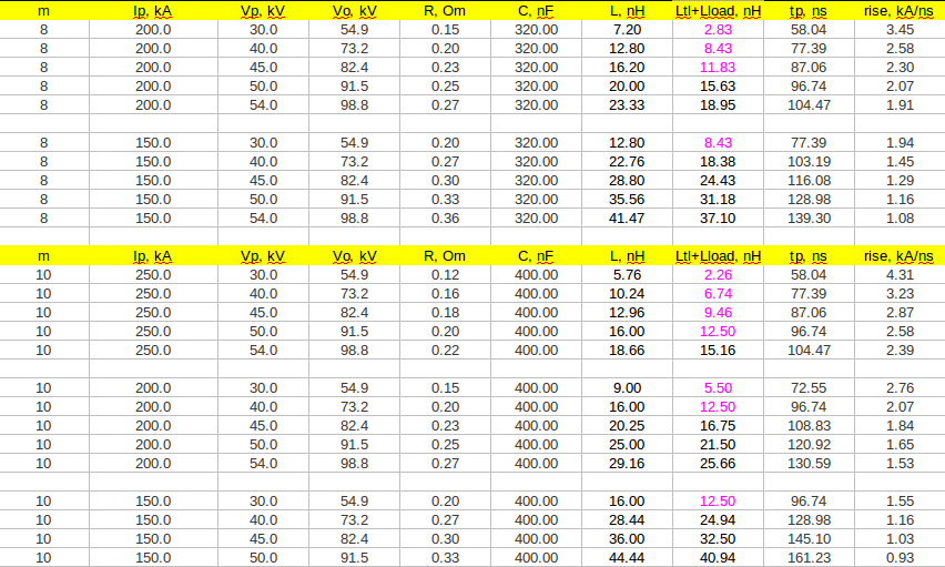
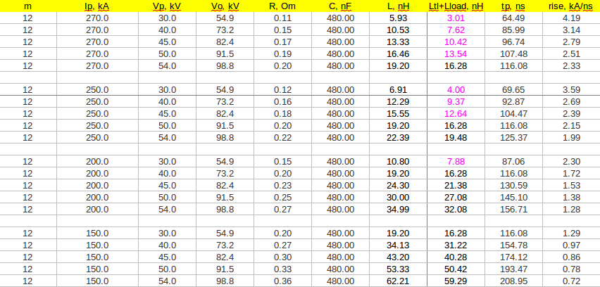
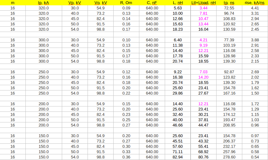
Below is example of optimization for m = 6, 8, 10, 12 and 16 cases. Here I first vary m, then Ip and then Vp.
Do not read it: It's funny. Say you want to make generator as small as possible device. Now the most important parameter of system is number of elements m. The best value for m will be the minimum values of m inside the range. Because we want for X-pinch generator the peak current is no less then 150 kA, the best number of element is 150 kA / 25 kA = 6. This will garant that we have the smallest compact facilities and we still satisfy the current peak values. Now let's very peak current. Here the only one possible value of peak current is 150 kA. So next vary the peak voltages. From all sett select only ones which are inside our constrain and from them select the best. But what the best. Say we do not satisfy. I really need to talk with Beezhold what we want.
Who know how to make the multidimensional multistep optimization with multiple constrains?


