Difference between revisions of "Development of Compact Plasma Radiation Source (CPRS) at IAC for imaging"
| Line 47: | Line 47: | ||
==Applications of X-Pinch== | ==Applications of X-Pinch== | ||
| − | * X-Ray point projection radiography (no pinhole) of | + | * X-Ray point-projection radiography (no pinhole) of |
** dense plasma, like exploding wires, X-Pinches, Z-Pinches | ** dense plasma, like exploding wires, X-Pinches, Z-Pinches | ||
** other objects | ** other objects | ||
Revision as of 05:21, 17 March 2013
- X-Pinch was proposed in 1982 at the P.N.Lebedev Physical Institute [1]
[1] S. M. Zakharov, G. V. Ivanenkov, A. A. Kolomenskii, S. A. Pikuz, A. I. Samokhin, and I. Ulshmid, "Wire X-pinch in a high-current diode", Sov. Tech. Phys. Lett., vol. 8, pp.456 -457 1982
To do
- Look at scaling: dependence of X-Ray source size, pulse duration and photon energy spectra upon the wire material and diameter, and the current waveform from the pulser. It could happens that for compact PRS, when current width is small, we will not have enough time to make X-Ray Pulse. Also, for imaging with good time resolution (for. Khalid), we want the smallest X-Ray pulse width (<1ns) without jitter and with good reproducibility
- see X-Pinch scaling below: [1]
- Look at diagnostics
- see X-Pinch diagnostics below: [2]
- Look at switches. Right now I have used Lsw = 10 nH (Mazarakis 1999 [3]). But if the switch inductance, say, is Lsw = 115 nH we will need at least 10 - 20 bricks (depending on kA/ns needed). If so, we do have anymore the compact PRS (4 capacitors). Now we are indeed coming toward to LTD cavity design..
- Look at voltage breakdown
- air: 3 kV/mm
- vacuum:
- Design idea
- make open easy access design
- use "critically damped" design to eliminate negative wave
- Look at compact X-Pinch design
- Find new idea for PhD (new physics/ new methods/ new application)
- new physics: impossible
- new design idea: nobody built X-Pinch Pulser based on new low inductance capacitors below 100 kA. We can build such compact portable X-Pinch facility at IAC. Plus, probably, nobody built X-Pinch Pulser which is broad scalable in I keeping dI/dt >1 kA/ns. Looks like X-Pinch machines based on low inductance capacitors are able to do this job (by changing capacitors's charging voltage). So we can study X-Pinch scaling law not only based on changing wire materials and diameters, but also by changing widely load current.
X-Pinch simulation parameters
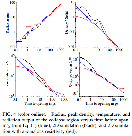
- "In this Letter we describe a theoretical investigation of the three phases of X-pinch evolution. We use as an example, experiments on theXPpulser at Cornell University where a current rising to 460 kA in 40 ns was used to drive two X pinches, each comprised of two 17 um molybdenum wires [6]. Using the GORGON [9] 3D resistive magnetohydrodynamics (MHD) code we show....."
- "...both models predict that at peak compression the plasma has collapsed to a micron in diameter and has reached solid density, the temperature is 2 keV the output power is 5 GW and the lifetime is 2 ps. These five parameters are then consistent with the faster time scale diagnostic results presented in Refs. [7,8]."
Applications of X-Pinch
- X-Ray point-projection radiography (no pinhole) of
- dense plasma, like exploding wires, X-Pinches, Z-Pinches
- other objects
- X-Ray monochromatic radiography (using a Bragg crystal reflector as a wavelength selector)
- X-ray phase-contrast radiography of low absorption objects
- X-Ray radiography of very fast event (<20 ps)
- rapidly change plasma
- living organism
- X-Ray micro-lithography
- Biological Objects
- house fly, fruit fly
- Medicine
- tissue sample
X-Pinch scaling
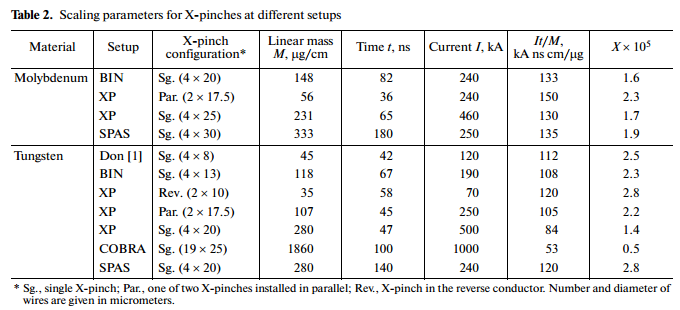
Scaling parameters: Dependence of X-Ray burst size, pulse duration, energy, power etc. upon the wire material, diameter, load current waveform and etc. from the pulser
- In spite of the fact that X-pinch has been studied for a long time on various setups, the scaling parameters for the initial conditions (current, rate of current rise, wire material, number of wires, linear mass of the load, and its configuration) for which the X-pinch is optimal are still unknown and are determined experimentally in each specific case. This is primarily due to the fact that X-pinch is a system that basically operates for a wide range of initial conditions. Second, processes in the X-pinch are quite complicated, and a theoretical model for an adequate description of all stages of these processes has not been constructed as yet. Third, systematic studies can only be performed on the same specific setup, and setups differ significantly. [4]
Scaling parameters for X-Pinches at different setups
"...Simple relations are proposed for choosing optimal initial parameters of the X-pinch for various types of current generators."
dI/dt > 1 kA/ns requirement
- "To obtain a bright source of radiation, i.e., an ∼1 µm or submicrometer-scalesize radiation source in the soft X-ray range that has a subnanosecond pulse duration, the generator must have a rate of the rise of current I that satisfies dI/dt > 1 kA/ns. Furthermore, the bigger this parameter is, the brighter the source can be." [6]
- "The main requirements imposed on the generator are the current amplitude 150-300 kA and the rate of the current rise 1-2 kA/ns. At the moment, these parameters of the current pulse can be provided only by enough large fixed-site generators weighing from 300 kg to several tons. These shortcomings limit to a great extent the feasibility of this diagnostic technique in studies of extreme states. Therefore, the design of a portable pulse generator which provides the required parameters makes it possible to proceed to a new level of diagnostics of fast processes." [7]
Single brighpoint source requirement
- "... matching the X-pinch wire mass to the specific current-pulse parameters is important in determining whether there will be a single brightpoint source rather than many bright spots and in minimizing the hard X-rays due to the energetic electrons."
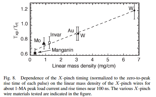
- "...If the current is near enough to the peak value that the derivative is decreasing in magnitude, the COBRA X-pinches can produce one intense X-ray burst in the > 1.7-keV energy region with more than 1-J energy yield and with a source size near 1 µm. ... . In the experiments, it was shown that the most important factor determining the first X-ray burst timing is the linear mass density.
- "...Fig. 8 shows that the most important factor for determining the first X-ray burst timing was the linear mass density of the wires."
Temporal and spectral characteristics of X-Ray
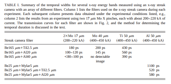
- "...However, there are substantial differences between materials. For example, the pulse duration for Al with filtering for energy >1.5 and >5 keV are about 1 and 0.5 ns, respectively. By contrast, for Mo with filtering for energy >2.5 and >5 keV, the pulse durations are about 200 ps and <80 ps, respectively."
- "...We found that the burst duration depends upon the wire material and the x-ray energy range. Using an x-ray streak camera, we determined that Mo-wire X pinches produce x-ray pulses that are about 200 ps long in 2.5–5 keV radiation and <80 ps with energy >5 keV."
- ".... It is shown that, for high-Z elements, the duration of the X-ray pulse in the short-wavelength part of the spectral range under study does not exceed 5−10 ps"
X Pinch Plasma Development as a Function of Wire Material and Current Pulse Parameters
- The timing of the first X-ray burst from an pinch depends upon the current derivative, the linear mass of the wires, and the wire material.
- In addition, the current waveform was shown to influence the pinch timing, but the wire size, for a given material and a given current pulse, has a relatively small effect.
- For more reproducible pinch performance, wires with intermediate and resistivity are best, giving predictable, low-jitter X-ray burst timing.
- If the current pulse being used is somewhat nonreproducible, or has a longer rise time, a more massive wire may provide reliable, lower jitter performance
- Higher wires tend to produce a background of more energetic X-rays in a relatively long, low-level pulse that is believed to be due to generation of an energetic electron beam across the pinch [20]. This can reduce the contrast available in radiographs obtained with higher materials such as W.
- It is now well known that low materials often produce multiple X-ray bursts and can have relatively large total source size, with the number decreasing as increases.
Radius scaling
- For example, the minimum radius scaling as r = I^(-14/9)*Z^(-10/9) suggests that in order to reach a radius of less than 1um requires a current of 100 kA for molybdenum, 516 kA for aluminum, but only 45 kA for tungsten, which is roughly consistent with experiments at Cornell University [6–8], at Pontificia Universidad Cato´lica de Chile [16], and at Imperial College [17].
Power
X-Pinch diagnostics
- Laboratory of Plasma Studies, Spectrometers [12]
- Laboratory of Plasma Studies, Streak-camera [13]
- Laboratory of Plasma Studies, XUV-cameras [14]
- Laboratory of Plasma Studies, Laser-backlighter [15]
- Laboratory of Plasma Studies, Interferometer [16]
- Plasma Laboratory - Weizmann Institute of Science, X-ray spectroscopy [17]
- Imperial College, Current Diagnostics [18]
: temporal X-Ray diagnostic
- extreme ultraviolet (XUV): X-Ray vacuum diodes (XRDs)
- soft X-ray (SXR): diamond photoconducting detectors (PCDs), < 5 - 8 kEV, resolution ~ 200 ps
- hard X-ray (HXR): Si-diodes (AXUV-HS), resolution ~ 700 ps, low sensitivity
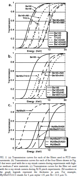
- energy filters. Examples
- Be 165: E > 2 keV
- Be 165 + Ti 12.5: 3 keV < E < 4.9 keV, E > 6 keV
- Be 165 + Al 20: E > 4 keV
- Be 165 + Al 40: E > 5 keV
- etc.
- see, for example, S. A. Pikuz, T. A. Shelkovenko, D. B. Sinars, D. A. Hammer. Temporal characteristics of X-ray emission from X-pinches. [19]
fast diagnostics
- streak camera with a step filter: slow camera ~ 100 ps, fast camera ~ 4 ps
- Tektronix TDS684B digital oscilloscope, bandwidth 2.5 GHz, sample rate of 10 GHz. $6,272[20]
: spatial X-Ray diagnostic
- [21]
- point-projection imaging to estimate the size of the X-Ray bright spots
- [22] [23]
- pinhole cameras with different filters
- slit camera with a step attenuator.
: spectral X-Ray diagnostic
- [24]
- focusing spectrograph with spatial resolution (FSSR) (based on spherically bent mica crystal spectrograph)
- convex crystal spectrograph
- flat KAP spectrograph
- pinhole cameras with different sets of filters
- a camera with a 50-µm slit and a step filter set (slit step-wedge (SSW) camera)
- To obtain time resolution, we meed fast streak camera (for example, a fast Kentech streak camera* capable of <10 ps time resolution can be used [25])
: dose rate/dose diagnostic
current and voltage monitoring
- Rogowski coils
- B-dot
- D-dot
energy filters
PRS based on Linear Transformer Driver (LTD) technologies
"The LTD driver is an induction generator similar to the induction accelerator (LIA) [1,2], the inductive voltage adder (IVA) [3–6], and the linear pulsed transformer (LPT)" [27]
Each LTD stage (or sometimes called LTD cavities) consists of three different elements: a capacitor, a gas spark switch and a ferromagnetic core. The necessity of ferromagnetic core is to inductively connect stage to TL. So the one stage can be used as building block to design the bigger facilities. Buy designing the different stages and connecting them in different way a great variety id devices can be constructed. [28]
What was done with LTD:
- A compact, high-voltage e-beam pulser: 3 MV, 100 kA
- A compact, high-voltage e-beam pulser: 10 MV, 100 kA
- 1 MV ultra-fast LTD generator: 1 MV, 125 kA
- High Current Fast 100-NS cavity: 100 kV, 1 MA
- LTD-II: 100 kV, 490 kA
- LTD-III: 92 kV, 810 kA
- etc...
Pulsed Power Company
- General Atomics Electronic Systems, Inc. (GA-ESI), San-Diego [29]
- General Atomics Electronic Systems, Inc.: Series PDS/PDSS - Fast Pulse Capacitors [30]
- Pulsed Power Laboratories. Inc [31]
- L-3 Applied Technologies - Pulse Sciences [32]
- L-3 Applied Technologies - Pulse Sciences: HV Switches [33]
What we need to build 200 kA, 100 ns, 0.25 Om pulse generator (20/02/13 presentation talk: plan #3)
- 4 capacitors 35477 (Cc=80 nF, Lc=10 nH , Vo=100 kV, I c=60 kA) [34]
- 4 switches (Lsw = 10 nH) ?
- high power resistors
- trigger system
- power supply
- diagnostics
- metals
- dielectrics
- manpower
Literature
Literature: LTD tehnologies
- M.G.Mazarakis, A compact, high-voltage e-beam pulser, 1999 IEEE [35]
- M.G.Mazarakis Ultrafast LTD's for bremsstrahlung diodes and Z-pinches 2002 IEEE [36]
- A.A.Kim 1 MV ultra-fast LTD generator 2003 IEEE [37]
- M.G.Mazarakis High Current Fast 100-NS LTD Driver Development in Sandia Laboratory 2005 IEEE [38]
- M.G.Mazarakis Conceptual Design for a Linear-Transformer Driver (LTD)-Based Refurbishment and Upgrade of the Saturn Accelerator Pulse-Power System SANDIA REPORT SAND2006-5811, 2006 [39]
- M.G. Mazarakis Linear Transformer Driver (LTD) development at Sandia national laboratory 2009 IEEE [40]
- J.R.Woodworth Low-inductance gas switches for linear transformer drivers Phys. Rev. ST Accel. Beams 12, 060401 (2009) [41]
- W.A.Stygar Shaping the output pulse of a linear-transformer-driver module Phys. Rev. ST Accel. Beams 12, 030402 (2009) [42]
- A.A. Kim Development and tests of fast 1-MA linear transformer driver stages Phys. Rev. ST Accel. Beams 12, 050402 (2009) [43]
- M.G. Mazarakis High current, 0.5-MA, fast, 100-ns, linear transformer driver experiments Phys. Rev. ST Accel. Beams 12, 050401 (2009) [44]
- M.G. Mazarakis High-Current Linear Transformer Driver Development at Sandia National Laboratories 2010 IEEE [45]
- J. R. Woodworth Compact 810 kA linear transformer driver cavity Phys. Rev. ST Accel. Beams 14, 040401 (2011) [46]
- S. C. Bott, D. M. Haas, R. E. Madden, U. Ueda, Y. Eshaq, G. Collins, IV, K. Gunasekera, D. Mariscal, J. Peebles, and F. N. Beg. 250 kA compact linear transformer driver for wire array z-pinch loads. Phys. Rev. ST Accel. Beams 14, 050401 (2011) [47]
