Determining wire-theta correspondence
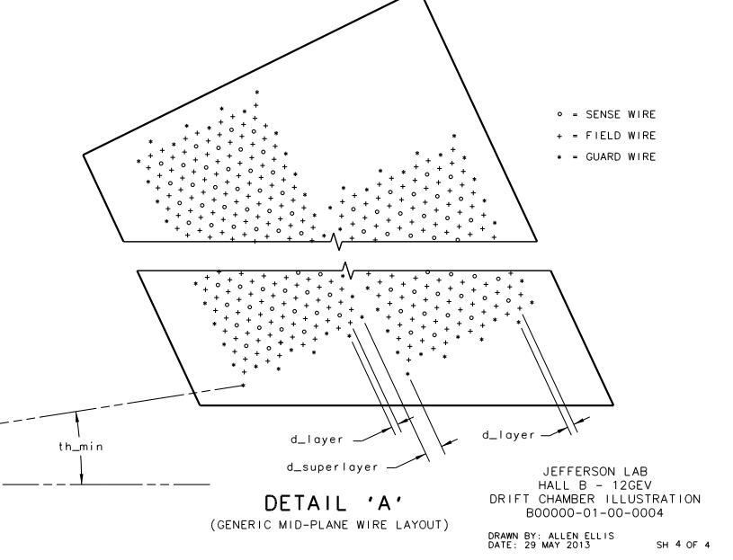
To associate the hits with the Moller scattering angle theta, the occupancy plots of the drift chamber hits by means of wire numbers and layer must be translated using the physical constraints of the detector. Using the data released for the DC:
DC: Drift Chambers(specs)
DC Geometry(geom)

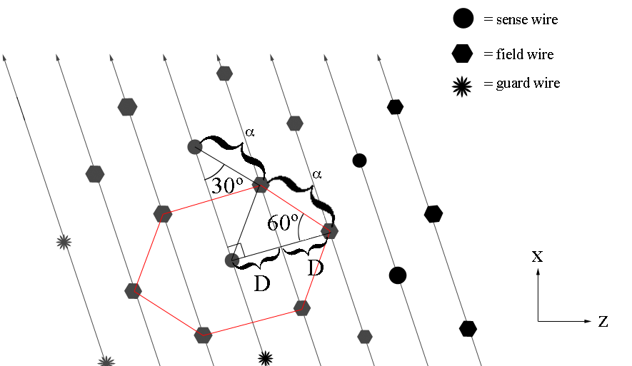
Examining the geometry file, we can see that each plane, not just the plane of the sense wires, is separated by a distance of D=.3861 cm. We can use the geometry of the wire placements to find
Finding the separation distance between two adjacent sense wires

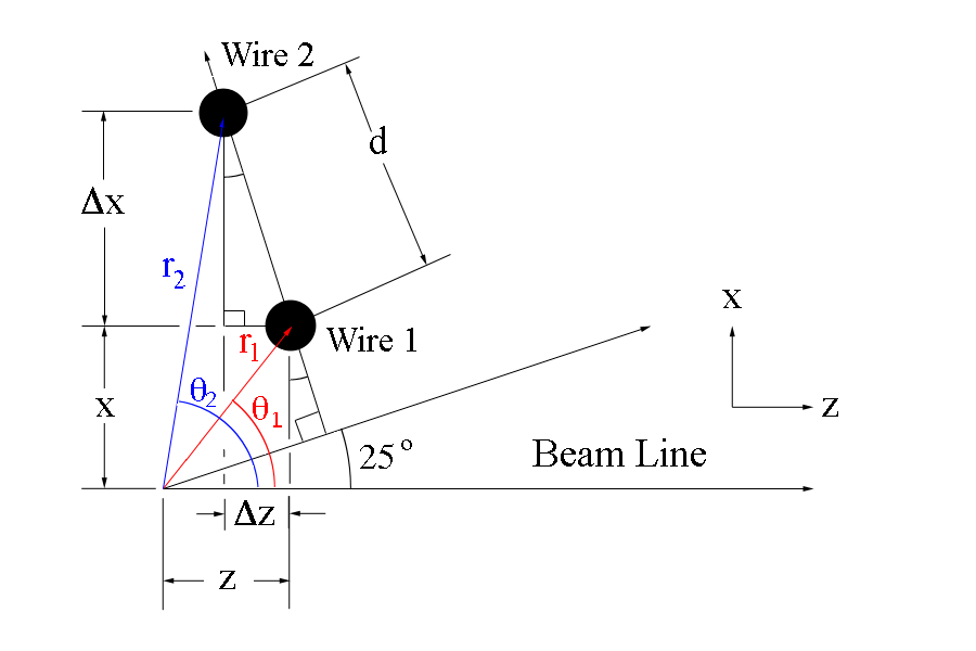
Since the separation between adjacent sense wires is uniform and at a set angle of 25 degrees with respect to the beam line, we can use this fact to determine the angle theta each wire makes when measured from the vertex.

The new x and z coordinates for wire 2 can be found using the change in the components
This can be extended to any point along the same wire plane, starting from the coordinates for wire 1
The angle theta that the wire makes with the vertex is given by