Determining and Verify Shield Limits
Revision as of 15:51, 27 October 2018 by Vanwdani (talk | contribs) (Created page with "File:MollerShieldDraftingView.png Images taken from cadBeamline/cadBeamlineFTOFF File:cadBeamlineFTon_Mathematica.pngFile:cadBeamlineFTOFF_Mathematica.png Dete...")
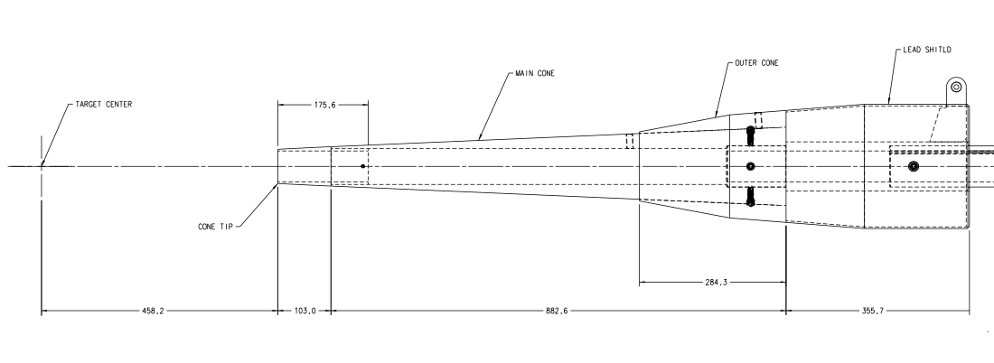
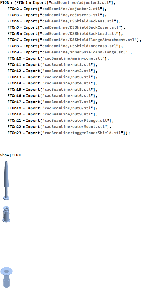
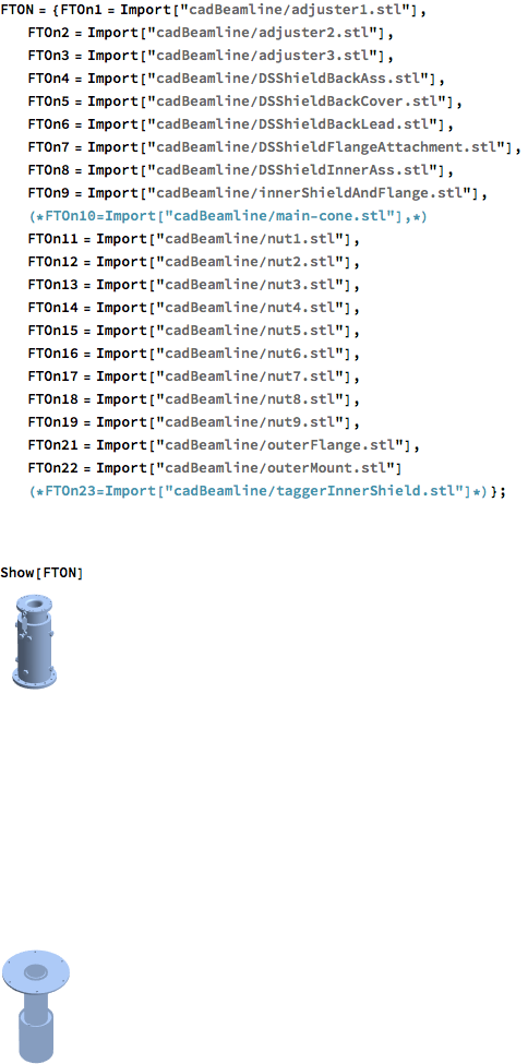
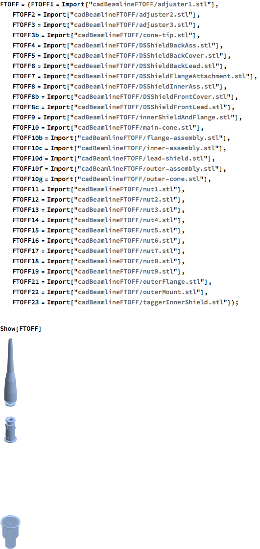
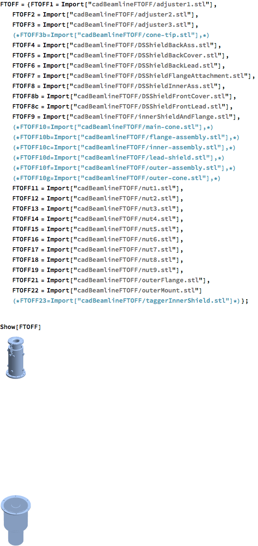
Images taken from cadBeamline/cadBeamlineFTOFF
Determining what the shield components are using Mathematica, gcards are modified to call Modified cadBeamline and cadBeamlineFTOFF files without the shield components.
FTOn_ShieldIn:
FtOn_ShieldOut:
FTOff_ShieldIn:
FTOff_ShieldOut:
According to cad.gxml within cadBeamline: For the FTON configurration the cone is shifted by -238.8mm
For integrating the rate within the shield area, this implies:
For the components of FTOff, starting at the cone-tip and running to the lead shield
For the component of FTOn, starting at the main-cone (the only component)
