Difference between revisions of "DV MollerTrackRecon"
| Line 112: | Line 112: | ||
\end{array} | \end{array} | ||
\right)</math> | \right)</math> | ||
| + | |||
| + | This shows how the coordinates are transformed and explains the validity of using the TBTracking information to obtain a phi angle in the lab frame. | ||
==Phi shifts== | ==Phi shifts== | ||
Revision as of 21:00, 22 October 2015
Moller events WITH Solenoid
LUND file with Moller events (with origin of coordinates occurring at each event)
2       1       1       1       1       0       0.000563654     3.53715 0       6.2002
1 -1 1 11 0 0 0.69 -2.4999 10993.7998 10993.80 0.000511 0 0 0
2 -1 1 11 0 0 -0.69 2.4999 6.5852 7.08 0.000511 0 0 0
From a GEMC run WITH the Solenoid ced is used to obtain the information from the eg12_rec.ev file.

We take the phi angle from the Simulated Event momentum as the initial phi angle. The obtain the final phi angle, we can look at the final position of the electron with in the drift chambers.

Examining the position from Timer Based Tracking, we can see that after rotations about first the y-axis, then the z-axis transforms from the detector frame of reference to the lab frame of reference.
For the rotation about the y axis.

And the rotation about the z axis.

Transformation Matrix
The Euler angles can be applied using a transformation matrix
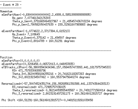
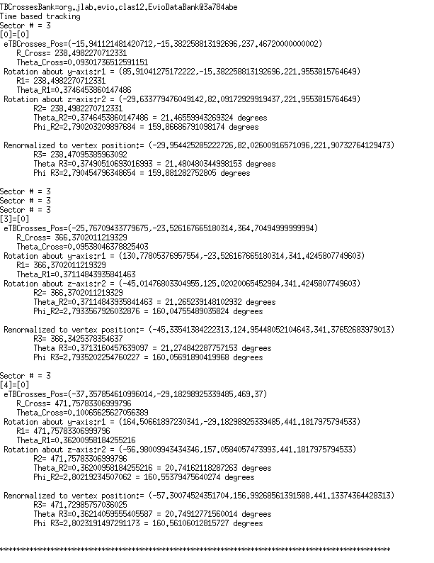
For event #29, in sector 3, the location of the first interaction is given by

Converting -25 degrees to radians,
which is the rotation the detectors are rotated from the y axis.
Finding since "sector -1" =3-1=2*60=120 degrees
This shows how the coordinates are transformed and explains the validity of using the TBTracking information to obtain a phi angle in the lab frame.
Phi shifts
This shows that the final position within the drift chambers is equal to the eTBTracking position. Normalizing the position with respect to the vertex location for the even, we can use the angle phi that this position makes with respect to origin to compare to the original phi from the momentum term to see if phi has shifted.
![]()
Collecting the Phi shifts as discussed above, for both with and without the Solenoid, and writing to separate data files, a root macro is written to plot the phi shifts.

The large shifts in phi occur for two reasons: Small Energy, and large angles in theta as shown in this sample of phi angles greater than 25°
