Difference between revisions of "DV Analyze Recon"
| (23 intermediate revisions by the same user not shown) | |||
| Line 126: | Line 126: | ||
=Analysis.groovy= | =Analysis.groovy= | ||
| + | ==Generating 4-Vector== | ||
From a GEMC run of solenoid field strength of 0T, the eg12_rec.0.evio output file of the reconstruction is analyzed. The different kinematic variables are displayed as shown: | From a GEMC run of solenoid field strength of 0T, the eg12_rec.0.evio output file of the reconstruction is analyzed. The different kinematic variables are displayed as shown: | ||
| Line 133: | Line 134: | ||
| − | <center><math>|\vec{p}_2\ '|=\sqrt{1.23162997^2+1.49707997^2+3.6786499^2}=4.15819983964</math></center> | + | <center><math>|\vec{p}_2\ '|=\sqrt{1.23162997^2+1.49707997^2+3.6786499^2}=4.15819983964\ GeV/c</math></center> |
| − | Using the expression found above for <math>theta</math> | + | Using the expression found above for <math>\theta</math> |
<center><math>\theta '_2=\arccos \left(\frac{p^'_{2(z)}}{p^'_{2}}\right)=\arccos \left(\frac{3.6786499}{4.15819983964}\right)=.4850027502\ Radians=27.7886106387\ degrees</math></center> | <center><math>\theta '_2=\arccos \left(\frac{p^'_{2(z)}}{p^'_{2}}\right)=\arccos \left(\frac{3.6786499}{4.15819983964}\right)=.4850027502\ Radians=27.7886106387\ degrees</math></center> | ||
| + | Similarly, using the expression found for <math>\phi</math> | ||
| + | |||
| + | |||
| + | <center><math>\phi '_2=\arccos \left( \frac{p^'_{2(x) Lab}}{p^'_{2(xy)}} \right)=\arccos \left( \frac{1.23162997}{1.93859764252} \right)=.882373425906\ Radians=50.5562732589\ degrees</math></center> | ||
| + | |||
| + | |||
| + | <center>where <math>p_{2(xy)}^'=\sqrt{(p_{2(x)}^')^2+(p^'_{2(y)})^2}=\sqrt{1.23162997^2+1.49707997^2}=1.93859764252\ GeV/c</math></center> | ||
We take the phi angle from the Generated Event momentum as the initial phi angle. | We take the phi angle from the Generated Event momentum as the initial phi angle. | ||
| + | ==Change of Generating Vector in eg12 detector== | ||
| − | The obtain the final phi angle, we can look at the final position of the electron with in the drift chambers. | + | The obtain the final phi angle, we can look at the final position of the electron with in the drift chambers. The drift chambers have their own unique coordinate system, which is a rotation |
| − | + | [[File:Event14_part2.png]] | |
Examining the position from Timer Based Tracking, we can see that after rotations about first the y-axis, then the z-axis transforms from the detector frame of reference to the lab frame of reference. | Examining the position from Timer Based Tracking, we can see that after rotations about first the y-axis, then the z-axis transforms from the detector frame of reference to the lab frame of reference. | ||
| − | =Euler Angles= | + | ===Euler Angles=== |
We can use the Euler angles to perform the rotations. | We can use the Euler angles to perform the rotations. | ||
For the rotation about the y axis. | For the rotation about the y axis. | ||
| − | [[File:Euler1.png]] | + | <center>[[File:Euler1.png]]</center> |
And the rotation about the z axis. | And the rotation about the z axis. | ||
| − | [[File:Euler2.png]] | + | <center>[[File:Euler2.png]]</center> |
| − | =Transformation Matrix= | + | =Transformation Matrix Verification= |
The Euler angles can be applied using a transformation matrix | The Euler angles can be applied using a transformation matrix | ||
| − | <math>\left( | + | <center><math>\left( |
\begin{array}{ccc} | \begin{array}{ccc} | ||
\cos (\theta ) & 0 & -\sin (\theta ) \\ | \cos (\theta ) & 0 & -\sin (\theta ) \\ | ||
| Line 183: | Line 192: | ||
z \cos (\theta )+x \sin (\theta ) \\ | z \cos (\theta )+x \sin (\theta ) \\ | ||
\end{array} | \end{array} | ||
| − | \right)</math> | + | \right)</math></center> |
| + | |||
| + | |||
| + | This can be verified using ced. | ||
| + | <pre> | ||
| + | ~/src/CLAS/coatjava-1.0/bin/ced | ||
| + | </pre> | ||
| − | For event # | + | For eg12_rec.0.evio, trial 1, for 0T, event #14, in sector 2, the location of the first interaction is given by |
| − | <center>[[File:conversions.png]]</center> | + | <center>[[File:conversions.png|800px]]</center> |
| − | + | Starting with the tilted xyz coordinates, we can use the fact that each paddle of the detecters is rotated -25 degrees from the y axis. Converting this into radians, we find | |
| − | <math>\theta =-0.436332</math> | + | <math>\theta=\frac{-25\ 2 \pi }{360} =-0.436332</math> |
| − | + | Using the Euler transformation matrix: | |
<math>\left( | <math>\left( | ||
| Line 207: | Line 222: | ||
\right).\left( | \right).\left( | ||
\begin{array}{c} | \begin{array}{c} | ||
| − | + | 9.26 \\ | |
0 \\ | 0 \\ | ||
| − | 237. | + | 237.27 \\ |
\end{array} | \end{array} | ||
\right)</math><math>=\left( | \right)</math><math>=\left( | ||
\begin{array}{c} | \begin{array}{c} | ||
| − | + | 108.667 \\ | |
0. \\ | 0. \\ | ||
| − | + | 211.126 \\ | |
\end{array} | \end{array} | ||
\right)</math> | \right)</math> | ||
| − | + | ||
| + | This shows the tilted xyzis equal to the sector xyz after a y axis rotation of -25 degrees. From this, each sector has a rotation of 60 degrees per sector number about the z axis. Using the relationship, | ||
| + | |||
| + | Sector Number-1=2-1=1 | ||
| + | |||
| + | We need one 60 degree rotation about the z-axis, or in radians: | ||
| + | |||
| + | |||
| + | <math>\phi =\frac{120\ 2 \pi }{360}=1.0471975512</math> | ||
| + | |||
| + | |||
| + | |||
| + | Using the Euler transformation for a z-axis rotation: | ||
<math>\left( | <math>\left( | ||
| Line 229: | Line 256: | ||
\right).\left( | \right).\left( | ||
\begin{array}{c} | \begin{array}{c} | ||
| − | + | 108.667 \\ | |
0. \\ | 0. \\ | ||
| − | + | 211.126 \\ | |
\end{array} | \end{array} | ||
\right)</math><math>=\left( | \right)</math><math>=\left( | ||
\begin{array}{c} | \begin{array}{c} | ||
| − | + | 54.3335 \\ | |
| − | + | 94.1084 \\ | |
| − | 221. | + | 221.126 \\ |
\end{array} | \end{array} | ||
\right)</math> | \right)</math> | ||
This shows how the coordinates are transformed and explains the validity of using the TBTracking information to obtain a phi angle in the lab frame. | This shows how the coordinates are transformed and explains the validity of using the TBTracking information to obtain a phi angle in the lab frame. | ||
| + | |||
| + | |||
| + | ---- | ||
| + | |||
| + | Links | ||
| + | |||
| + | [[DV_RunGroupC_Moller#Analyzing_Reconstruction_Data|Back]] | ||
Latest revision as of 22:31, 30 March 2016
Calculating kinematic variables in Moller Lab Frame
Vector Magnitude
The pythagorean theorem is used to take the 3 cartesean components in the Lab frame to find the magnitude of the Moller momentum vector, .
Finding the correct kinematic values starting from knowing the momentum of the Moller electron, , in the Lab frame,
xz Plane

Checking on the sign resulting from the cosine function, we are limited to:
Since,
xy Plane

and results based on
Checking on the sign from the cosine results for
We have the limiting range that must fall within:

Examining the signs of the components which make up the angle in the 4 quadrants which make up the xy plane:
Analysis.groovy
Generating 4-Vector
From a GEMC run of solenoid field strength of 0T, the eg12_rec.0.evio output file of the reconstruction is analyzed. The different kinematic variables are displayed as shown:
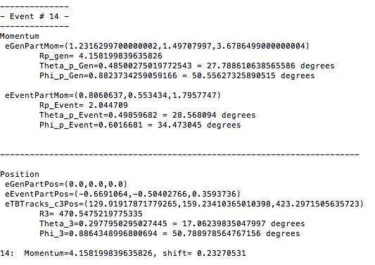

Using the phythagorean theorm to construct the Generated Event momentum vector length, we find:
Using the expression found above for
Similarly, using the expression found for
We take the phi angle from the Generated Event momentum as the initial phi angle.
Change of Generating Vector in eg12 detector
The obtain the final phi angle, we can look at the final position of the electron with in the drift chambers. The drift chambers have their own unique coordinate system, which is a rotation

Examining the position from Timer Based Tracking, we can see that after rotations about first the y-axis, then the z-axis transforms from the detector frame of reference to the lab frame of reference.
Euler Angles
We can use the Euler angles to perform the rotations.
For the rotation about the y axis.

And the rotation about the z axis.

Transformation Matrix Verification
The Euler angles can be applied using a transformation matrix
This can be verified using ced.
~/src/CLAS/coatjava-1.0/bin/ced
For eg12_rec.0.evio, trial 1, for 0T, event #14, in sector 2, the location of the first interaction is given by

Starting with the tilted xyz coordinates, we can use the fact that each paddle of the detecters is rotated -25 degrees from the y axis. Converting this into radians, we find
Using the Euler transformation matrix:
This shows the tilted xyzis equal to the sector xyz after a y axis rotation of -25 degrees. From this, each sector has a rotation of 60 degrees per sector number about the z axis. Using the relationship,
Sector Number-1=2-1=1
We need one 60 degree rotation about the z-axis, or in radians:
Using the Euler transformation for a z-axis rotation:
This shows how the coordinates are transformed and explains the validity of using the TBTracking information to obtain a phi angle in the lab frame.
Links