Difference between revisions of "DV Analyze Recon"
| Line 4: | Line 4: | ||
[[File:Event14.png]] | [[File:Event14.png]] | ||
| − | We take the phi angle from the Generated Event momentum as the initial phi angle. The obtain the final phi angle, we can look at the final position of the electron with in the drift chambers. | + | Using the phythagorean theorm to construct the Generated Event momentum vector length, we find: |
| + | |||
| + | <center><math>r=\sqrt{1.23162997^2+1.49707997^2+3.6786499^2}=4.15819983964</math></center> | ||
| + | |||
| + | We take the phi angle from the Generated Event momentum as the initial phi angle. | ||
| + | |||
| + | |||
| + | The obtain the final phi angle, we can look at the final position of the electron with in the drift chambers. | ||
[[File:Event14_part2.png]] | [[File:Event14_part2.png]] | ||
Revision as of 18:03, 30 March 2016
Analysis.groovy
From a GEMC run of solenoid field strength of 0T, the eg12_rec.0.evio output file of the reconstruction is analyzed. The different kinematic variables are displayed as shown:
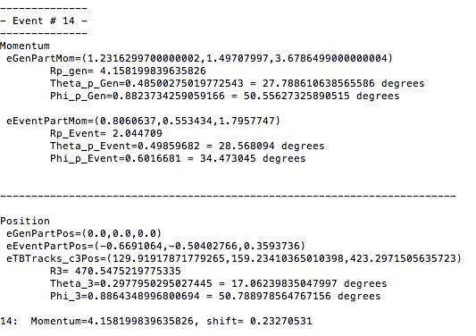

Using the phythagorean theorm to construct the Generated Event momentum vector length, we find:
We take the phi angle from the Generated Event momentum as the initial phi angle.
The obtain the final phi angle, we can look at the final position of the electron with in the drift chambers.
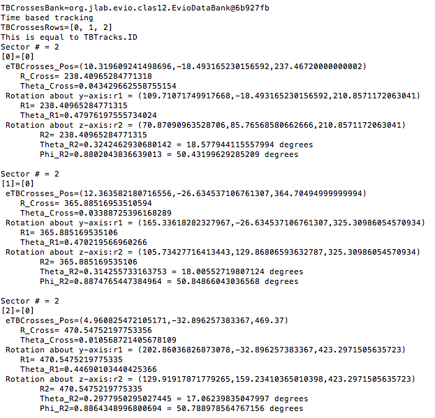

Examining the position from Timer Based Tracking, we can see that after rotations about first the y-axis, then the z-axis transforms from the detector frame of reference to the lab frame of reference.
Euler Angles
We can use the Euler angles to perform the rotations.
For the rotation about the y axis.

And the rotation about the z axis.

Transformation Matrix
The Euler angles can be applied using a transformation matrix
For event #29, in sector 3, the location of the first interaction is given by

Converting -25 degrees to radians,
which is the rotation the detectors are rotated from the y axis.
Finding since "sector -1" =3-1=2*60=120 degrees
This shows how the coordinates are transformed and explains the validity of using the TBTracking information to obtain a phi angle in the lab frame.