CLAS12R1 CosmicTestStand
Apparatus
| Label | Distance (cm) |
| 4 | |
| 4 | |
| 27.3 | |
| 34 | |
| 41 |
Scintillators
Two scintillators are placed on top and below the drift chamber
These scintillators have PMTs on both ends allow an initial position to be determined according to the time difference between the PMT hits.
Below is the calibration for Detector M and Detector G
HV(M1) = -1602 Volts
HV(M2) = -1750 Volts
Normalized_and_BKG_subtracted_data_for_Det_M
M2 PMT is not making good contact with the light guide thus output pulses are below 300 mV, Pulses get bigger and more frequent if you push the PMT onto the scintilator.
HV(G1)= -1700 Volts HV(G2)= -1650 Volts
Normalized_and_BKG_subtracted_data_for_Det_G
G1 pulses were below expectations ( below 300 mV?) perhaps the PMT is not capturing the light.
M1 = TDC80
M2 = TDC81
G1 = TDC84
G2 = TDC86
Trig = TDC 95
M1 = TDC112 M2 = TDC113 G1 = TDC116 G2 = TDC118 Trig = TDC 127
Trigger Matching is ON
resolution = 100 ps
Scint Time Difference
On Ortec model 934 Constant Fraction is used on the scintillator PMTs. The output width is 20 ns.
The CFD output is sent to a CAEN N455 quad coincidence logic unit. The logic unit output is set to 30 ns as the CAEN TDC 1990A requires a minimum TDC stop NIM signal of 25 ns.
Scint on top of each other
Before placing the scintillators at the locations shown above (one scint on each side of the drift chamber) we placed them on top of each other to measure the time between pulses when a cosmic ray passes through each. The Logic module width was 20 ns.
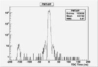
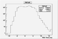
The time difference between two 4 cm thick scintillators placed on top of each other was measured. There seems to be 20 nsec wide time difference between the scintillator pulses in coincidence.
Scintillators on both sides of DC
We ran cosmic over the weekend and stored the data in run 3811.
Scintillator Timing Studies
- Test impact of timing pulse width on PMT time difference spectra.
| Run # | Date | CFD Width output | Coincidence output |
| 3832 | 1/22/13 | 20 | 30 |
| 3834 | 1/22/13 | 40 | 30 |
| 3835 | 1/22/13 | 80 | 30 |
- Rotated top scintillator so PMTs in use are on the same side of the chamber.
| Run # | Date | CFD Width output | Coincidence output |
| 3836 | 1/23/13 | 80 | 30 |
| 3837 | 1/23/13 | 40 | 30 |
| 3838 | 1/23/13 | 20 | 30 |
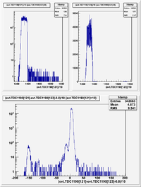
The time difference (T1-T2) between cosmic hits in the two scintillators placed on top of each other was compared for the case where the PMTs are on opposite ends of the scintillator to the case where the PMTs are adjacent to each other. The scintillators only have one PMT on and not both. We found the one PMT on each of the two scintillators was producing a lot of noise on the ground so we could only run each scintillator with 1 PMT.
PMTs that are adjacent to each other have a coincidence timing distribution which has a single dominant peak with an RMS of about 1.5 ns. If the top paddle is rotated 180 degrees so the coincidence formed is from PMTs that are on opposite sides, then we get 2 peaks.


