Difference between revisions of "CHIPS IAC Run 5-28-08"
| (27 intermediate revisions by the same user not shown) | |||
| Line 1: | Line 1: | ||
Delay from gun is about 400 ns | Delay from gun is about 400 ns | ||
gate width between 400 and 800 ns | gate width between 400 and 800 ns | ||
| + | |||
| + | |||
| + | = Beam Scans = | ||
| + | == '''Zero Degree Port.''' == | ||
| + | |||
| + | Beam spot at the Zero Degree Port as a function of grid voltage knob setting -- not calibrated to voltage but reproducible. (Settings: 0.1, 0.15, 0.18, 0.2) | ||
| + | |||
| + | [[Image:ZeroPort_10MeV_Gun2keV_Grid_0.1.jpg | 200 px]] | ||
| + | [[Image:ZeroPort_10MeV_Gun2keV_Grid_0.15.jpg | 200 px]] | ||
| + | [[Image:ZeroPort_10MeV_Gun2keV_Grid_0.18.jpg | 200 px]] | ||
| + | [[Image:ZeroPort_10MeV_Gun2keV_Grid_0.20.jpg | 200 px]] | ||
| + | |||
| + | |||
| + | |||
| + | |||
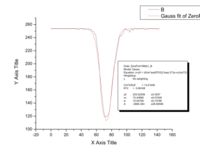
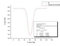
| + | The 0.15 grid setting is nice. It does not saturate. Here we take slices in x and y and then fit gaussians to the intensity curves. | ||
| + | We observe that 35 mm is 244 pix by comparing with the 3.5 cm distance between diagonal bolt studs. | ||
| + | |||
| + | [[Image:ZeroPort10MeV-0.15-leftright-slice.pdf]] | ||
| + | [[Image:ZeroPort10MeV-0.15-updown-slice.pdf]] | ||
| + | |||
| + | [[Image:ZeroPort10MeV-0.15-leftright-slice.jpg | 200 px]] | ||
| + | [[Image:ZeroPort10MeV-0.15-updown-slice.jpg | 200 px]] | ||
| + | |||
| + | |||
| + | <math>\sigma = \frac{w}{2} \frac{35}{244} </math> renders the standard deviation into mm. | ||
| + | The FWHM is <math> 2.35\sigma </math>. For the slices at the 0.15 setting, the FWHM are: <math> 2.35\sigma_x = 2.5 </math>mm and <math> 2.35\sigma_y = 2.7 </math>mm. This is fully consistent with our digital photographs taken on May 27, 2008. | ||
| + | |||
| + | == '''90 Degree Port.''' == | ||
| + | Beam spot at the 90 Degree Port as a function of grid voltage knob setting -- not calibrated to voltage but reproducible. (Settings: 0.61, 0.80, 1.23, 1.50) | ||
| + | [[Image:90Port_10MeV_Gun2keV_Grid_0.61.JPG| 200 px]] | ||
| + | [[Image:90Port_10MeV_Gun2keV_Grid_0.80.JPG| 200 px]] | ||
| + | [[Image:90Port_10MeV_Gun2keV_Grid_1.23.JPG| 200 px]] | ||
| + | [[Image:90Port_10MeV_Gun2keV_Grid_1.50.JPG| 200 px]] | ||
| + | |||
= Tune 4 MeV electrons into Experimental Cell= | = Tune 4 MeV electrons into Experimental Cell= | ||
| + | ==Tune parameters== | ||
Optics elements 45Q2, Bend2, L90Q1m L90Q2 are after the tungsten converter. | Optics elements 45Q2, Bend2, L90Q1m L90Q2 are after the tungsten converter. | ||
| Line 38: | Line 74: | ||
|Grid|| 4.84 | |Grid|| 4.84 | ||
|- | |- | ||
| − | | | + | |1202 || 13.2 kV |
|- | |- | ||
|SOL1 || 0.00 | |SOL1 || 0.00 | ||
| Line 51: | Line 87: | ||
[[Image:IAC-xmission-28May08.jpg | 200 px]] | [[Image:IAC-xmission-28May08.jpg | 200 px]] | ||
| − | = | + | ==MPA Runs== |
| − | |||
| − | |||
| − | + | The runs below had about 40 mA peak before the first 45 degree bend. | |
| − | |||
| − | |||
| − | |||
| + | Na-22 beta decays giving off a 215 keV KE beta and a 1.275 MeV photon. | ||
| + | Co-60: decays to Ni giving 2 dominant gamma lines at 1.173237( 4) and | ||
| + | 1.332501( 5) MeV. The Average Beta energy is 95 keV. | ||
| − | + | Using runs 7 and 9 I see the following | |
| − | |||
| − | |||
| − | |||
| − | |||
| − | |||
| − | |||
| − | |||
| − | |||
| − | |||
| − | |||
| − | |||
| − | |||
| − | |||
[[Image:NaICalib_PositronRuns13-14.gif]] | [[Image:NaICalib_PositronRuns13-14.gif]] | ||
| Line 103: | Line 124: | ||
|14|| NaI014.mpa || IN || Out|| Start Time: 14:08, Stop Time: 14:37 | |14|| NaI014.mpa || IN || Out|| Start Time: 14:08, Stop Time: 14:37 | ||
|- | |- | ||
| − | |15|| NaI015.mpa || IN || Out|| Install sweep magnet (electrons sweeping up or down, , Start Time: 14:49, Stop Time: 15:19 | + | |15|| NaI015.mpa || IN || Out|| Install 1kG sweep magnet (electrons sweeping up or down, , Start Time: 14:49, Stop Time: 15:19 |
|- | |- | ||
|16|| NaI016.mpa || IN || In|| Install sweep magnet (electrons sweeping up or down, , Start Time: 15:20, Stop Time: | |16|| NaI016.mpa || IN || In|| Install sweep magnet (electrons sweeping up or down, , Start Time: 15:20, Stop Time: | ||
| + | |} | ||
| + | |||
| + | =Tune for Max signal on NaI = | ||
| + | |||
| + | |||
| + | {| border="1" |cellpadding="20" cellspacing="0 | ||
| + | |- | ||
| + | |Run # || MPA file name || W || Ta || Description | ||
| + | |- | ||
| + | |18|| NaI018.mpa || IN || IN ||Start Time: 16:17, Stop Time: 16:32,Change last dipole to increase count rate on NaI (before were were getting an NaI pulse for about every 30 Gun pulses) | ||
| + | |- | ||
| + | |19|| NaI019.mpa || IN || Out|| Start Time: 16:32, Stop Time: 16.47 | ||
| + | |- | ||
| + | |20|| NaI020.mpa || IN || In|| Start Time: 16:49, Stop Time: Rep rate changed from 60 to 300 Hz | ||
| + | |- | ||
| + | |21|| NaI021.mpa || IN || In|| Start Time: , Stop Time: Change last dipole for electrons | ||
|} | |} | ||
[http://www.iac.isu.edu/mediawiki/index.php/CHIPS_Run_May-2008 Go Back] | [http://www.iac.isu.edu/mediawiki/index.php/CHIPS_Run_May-2008 Go Back] | ||
Latest revision as of 17:22, 9 July 2008
Delay from gun is about 400 ns gate width between 400 and 800 ns
Beam Scans
Zero Degree Port.
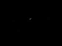
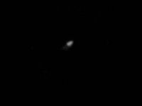
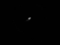
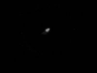
Beam spot at the Zero Degree Port as a function of grid voltage knob setting -- not calibrated to voltage but reproducible. (Settings: 0.1, 0.15, 0.18, 0.2)
The 0.15 grid setting is nice. It does not saturate. Here we take slices in x and y and then fit gaussians to the intensity curves.
We observe that 35 mm is 244 pix by comparing with the 3.5 cm distance between diagonal bolt studs.
File:ZeroPort10MeV-0.15-leftright-slice.pdf File:ZeroPort10MeV-0.15-updown-slice.pdf
renders the standard deviation into mm.
The FWHM is . For the slices at the 0.15 setting, the FWHM are: mm and mm. This is fully consistent with our digital photographs taken on May 27, 2008.
90 Degree Port.
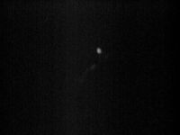
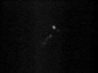
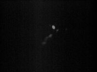
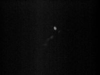
Beam spot at the 90 Degree Port as a function of grid voltage knob setting -- not calibrated to voltage but reproducible. (Settings: 0.61, 0.80, 1.23, 1.50)
Tune 4 MeV electrons into Experimental Cell
Tune parameters
Optics elements 45Q2, Bend2, L90Q1m L90Q2 are after the tungsten converter.
| Device | setting |
| RS1 | -0.46 |
| RS2 | +0.77 |
| FS1 | -0.68 |
| FS2 | 0.00 |
| 0Q1 | +0.76 |
| 0Q2 | +0.94 |
| 45Q1 | +0.02 |
| 45Q2 | +1.37 |
| L90Q1 | -2.98 |
| L90Q2 | +0.98 |
| Bend1 | +1.42 |
| Bend2 | +10.66 |
| Gun HV | 20 kV |
| Grid | 4.84 |
| 1202 | 13.2 kV |
| SOL1 | 0.00 |
| SOL2 | 8.59 |
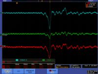
Here is an image of the transmission. Channel-2 minus Channel-4 (FC - flange).
MPA Runs
The runs below had about 40 mA peak before the first 45 degree bend.
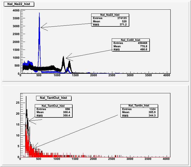
Na-22 beta decays giving off a 215 keV KE beta and a 1.275 MeV photon.
Co-60: decays to Ni giving 2 dominant gamma lines at 1.173237( 4) and 1.332501( 5) MeV. The Average Beta energy is 95 keV.
Using runs 7 and 9 I see the following
| Run # | MPA file name | W | Ta | Description |
| 6 | NaI006.mpa | NA | NA | Background measurement, no source |
| 7 | NaI007.mpa | NA | NA | Na-22 source on top of NaI detector |
| 8 | NaI008.mpa | NA | NA | change spec amp gain from 500 to 200 |
| 9 | NaI009.mpa | NA | NA | Co-60 source on top of NaI, Na-22 removed, Spec amp gain back to 500 |
| 10 | NaI010.mpa | NA | NA | change spec amp gain from 500 to 1000, put Na-22 and Co-60 on top of Nai |
| 11 | NaI011.mpa | IN | IN | ADC free running, change spec amp gain to 500, took out sources |
| 12 | NaI012.mpa | IN | IN | ADC gated with Gun, change spec amp gain to 500, took out sources |
| 13 | NaI013.mpa | IN | IN | Start Time: 13.27, Stop Time: 14:06 |
| 14 | NaI014.mpa | IN | Out | Start Time: 14:08, Stop Time: 14:37 |
| 15 | NaI015.mpa | IN | Out | Install 1kG sweep magnet (electrons sweeping up or down, , Start Time: 14:49, Stop Time: 15:19 |
| 16 | NaI016.mpa | IN | In | Install sweep magnet (electrons sweeping up or down, , Start Time: 15:20, Stop Time: |
Tune for Max signal on NaI
| Run # | MPA file name | W | Ta | Description |
| 18 | NaI018.mpa | IN | IN | Start Time: 16:17, Stop Time: 16:32,Change last dipole to increase count rate on NaI (before were were getting an NaI pulse for about every 30 Gun pulses) |
| 19 | NaI019.mpa | IN | Out | Start Time: 16:32, Stop Time: 16.47 |
| 20 | NaI020.mpa | IN | In | Start Time: 16:49, Stop Time: Rep rate changed from 60 to 300 Hz |
| 21 | NaI021.mpa | IN | In | Start Time: , Stop Time: Change last dipole for electrons |
