Difference between revisions of "CHIPS IAC Run 5-27-08"
Jump to navigation
Jump to search
| Line 14: | Line 14: | ||
[[Image:CHIPS_IAC_5-27-08_90DegreePort_MinSpotSize.jpg | 200 px]] | [[Image:CHIPS_IAC_5-27-08_90DegreePort_MinSpotSize.jpg | 200 px]] | ||
[[Image:CHIPS_IAC_5-27-08_90DegreePort_MinSpotSize_20MicroAmps.jpg | 200 px]] | [[Image:CHIPS_IAC_5-27-08_90DegreePort_MinSpotSize_20MicroAmps.jpg | 200 px]] | ||
| + | |||
| + | |||
| + | {| border="1" |cellpadding="20" cellspacing="0 | ||
| + | |- | ||
| + | |Device || setting | ||
| + | |- | ||
| + | | RS1 || 0+ | ||
| + | |- | ||
| + | | RS2 || 0- | ||
| + | |- | ||
| + | |FS1 || 0+ | ||
| + | |- | ||
| + | |FS2 || 0- | ||
| + | |- | ||
| + | |0Q1 || -2.62 | ||
| + | |} | ||
=Max Transmission= | =Max Transmission= | ||
Revision as of 16:11, 27 May 2008
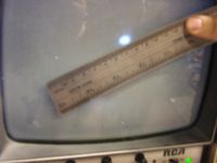
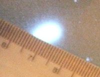
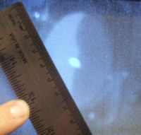
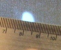
Beam Tuning pictures:
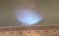
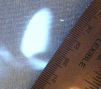
Smallest beam spot at 0 Degree port
The beam appears to light up a 3 mm diameter circle on the Phosphorus screen.
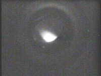
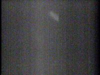
Smallest beam spot at 90 Degree port
The beam appears to light up a diameter circle on the Phosphorus screen with of beam current.
| Device | setting |
| RS1 | 0+ |
| RS2 | 0- |
| FS1 | 0+ |
| FS2 | 0- |
| 0Q1 | -2.62 |
Max Transmission
Retune machine to maximize transmission between the FC collar and the FC.
Using FrameGrabber
