Beamline design (Y. Kim)
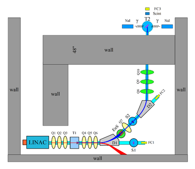
Beam Line Design
Need: more X-Y steerers(1 set after 1st triplet), belows at the exit of Linac, Torroid loop at exit of Linac, fast shutdown valve at Linac exit.
Distances
| Element | Distance to Center | Stancari Design |
| End of LinacGate Valve | 0.000 m | |
| Q1@T1 | 0.175 m | |
| Q2@T1 | 0.425 m | |
| Q3@T1 | 0.675 m | |
| TCOL1 | 1.025 m | |
| 1STTG | 1.175 m | |
| Q1@T2 | 1.400 m | 1.4 |
| Q2@T2 | 1.650 m | 1.6 (Yujong has 5 cm more space between quads) |
| Q3@T2 | 1.900 m | 1.8 |
| TCOL2 | 2.250 m | |
| KIWI1 | 2.525 m | 2.201 (Yujong has 22.4 cm more distance between last quad and dipole) |
| SLIT | 2.851 m | |
| Q1@DM | 3.026 m | 2.615 (Yujong has 8.7 more cm between dipole and quad) |
| SCREEN | 3.296 m | |
| KIWI2 | 3.617 m | |
| Q1@T3 | 4.063 m | Yujong has 29.1 cm leess distance between last dipole and quad) |
| Q2@T3 | 4.603 m | |
| Q3@T3 | 5.143 m | |
| SCREEN | 5.712 m | |
| 2NDTG | 6.112 m | |
| HOLE@WALL | 6.412 m |
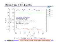
Beam Optics
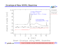
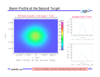
Beam Size
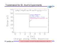
Expected electron Transmission
- Assuming a 9 mm wide slit in between the kiwi dipoles.
