Difference between revisions of "12 10 2012 HRRL DetectorTests"
| (37 intermediate revisions by 2 users not shown) | |||
| Line 10: | Line 10: | ||
[[HRRL_Dec_13_2012Run]] | [[HRRL_Dec_13_2012Run]] | ||
| + | |||
| + | |||
| + | |||
| + | =12/14/12= | ||
| + | |||
| + | Worked on establishing a small spot size on the Phosphorous target and then documenting the beam properties. | ||
| + | |||
| + | [[HRRL_Dec_14_2012Run]] | ||
| + | |||
| + | =12/19/12= | ||
| + | |||
| + | [[HRRL_Dec_19_2012Run]] | ||
| + | |||
| + | When Target T1 goes in and Accelerator side lights up( as viewed by scintillator Kelly) and Illyusha (when next to the beam exit window) also lights. | ||
| + | |||
| + | There is no Pb around T1. | ||
| + | |||
| + | Lets directionally shield Illyusha (when positioned next to the hallway) to determine how much lead to add around T1. | ||
| + | |||
| + | |||
| + | ADC3 = NaI Left | ||
| + | ADC7 = NaI Right | ||
| + | |||
| + | TDC 29 = NaI right | ||
| + | |||
| + | TDC 31 = NaI left | ||
| + | |||
| + | {| border="1" | ||
| + | | Area || Conditions | ||
| + | |- | ||
| + | |800 \pm 130 pVs|| No shielding T1 in | ||
| + | |- | ||
| + | |1600 \pm 200 pVs || 1 Pb brick (2") shielding T1 in Add Pb and signal goes up? Just noise! | ||
| + | |- | ||
| + | | || Move Illyusha so it is right next to experimental side flag, no shielding. | ||
| + | |- | ||
| + | |} | ||
| + | |||
| + | ==Take data using 3 MeV electrons on the T2 target. == | ||
| + | |||
| + | The Scintillator known as Kelly is has an output of about 1 Volt. | ||
| + | |||
| + | {| border="1" | ||
| + | | Run # || Configuration | ||
| + | |- | ||
| + | |4611|| T1 and T2 are in, Veto discrimnator, ADC overflows , TDC31-TDC29 looks OK, 25 Hz counting rate | ||
| + | |- | ||
| + | |4612|| T1 and T2 are in, Veto discrimnator, cut the beam current in half, rate is 0.06 Hz | ||
| + | |- | ||
| + | |4613|| T1 and T2 are in, Veto discrimnator, cut the beam current in half, rate is 4 Hz, lowered threshold from 20 to 7 mV | ||
| + | |- | ||
| + | |4614|| T1 in '''T2 out''', Veto discrimnator, cut the beam current in half, rate is 0.03 Hz | ||
| + | |- | ||
| + | |} | ||
| + | |||
| + | ==Take data using 3 MeV '''Positrons''' on the T2 target. == | ||
| + | |||
| + | The Scintillator known as Kelly is has an output of about 1 Volt. | ||
| + | |||
| + | ADC9 = NaI right | ||
| + | |||
| + | {| border="1" | ||
| + | | Run # || Configuration | ||
| + | |- | ||
| + | |4621|| T1 and T2 are in, Veto discrimnator, threshold is 5 mV, Kelly at 3.5 Volt ,rate is 0.2 Hz | ||
| + | |} | ||
| + | |||
| + | =12/20/2012= | ||
| + | |||
| + | [[HRRL_Dec_20_2012Run]] | ||
| + | ==RF noise measurement== | ||
| + | |||
| + | {| border="1" | ||
| + | | Run # || Configuration || ADC3 || ADC9 | ||
| + | |- | ||
| + | |4625|| Na-22 Source run with RF no beam current || [[File:r4625_ADC3.png | 200 px]]|| [[File:r4625_ADC9.png | 200 px]] | ||
| + | |} | ||
| + | |||
| + | {| border="1" |cellpadding="20" cellspacing="0 | ||
| + | |- | ||
| + | | run# || Mode and Energy || T1 || T2 || Sweep Magnet|| D1 and D2 (Amp) || logic || HV NaI Left (CH3) (Det#1) || HV NaI R Right (CH9) (Det#2) ||Dis Threshold Left ||Dis Threshold Right || Reprate || start || stop || Run time (s)|| Int Rate ||comments || event || pulses | ||
| + | |- | ||
| + | | 4623 || 3 MeV e+ on T2 ||in || in || out|| 5.8, 5.8 || (NaIL & GunTrig) & (NaIR & GunTrig) || 1100V || 1190V || 5 mV || 5 mV|| 300 || 16:43:26|| 16::|| || events/s|| beam pulses || || | ||
| + | |- | ||
| + | |} | ||
| + | |||
| + | {| border="1" |cellpadding="20" cellspacing="0 | ||
| + | |- | ||
| + | | Run # || Source || logic || Run starts || Run ends || HV NaI Left (CH3) (Det#1) || HV NaI R Right (CH9) (Det#2) || Spectrum | ||
| + | |- | ||
| + | | 4624 || Na22 || NaI Right && NaI Left || 19:42:36 || 08:03:30 next day || 1100 V || 1190 V || || | ||
| + | |||
| + | |} | ||
| + | |||
| + | RF adds 50 channels of noise to NaI signal and moves Source peak forward. | ||
| + | |||
| + | RF was for 3 MeV electrons, perhaps RF for higher energy electrons will add the remaining 30 channels of noise on the NaI detectors. | ||
| + | |||
| + | [[File:NaINoise_232425.png | 200 px]] | ||
| + | |||
| + | ==Positron attempt== | ||
| + | |||
| + | {| border="1" | ||
| + | | Run # || Configuration || ADC3 || ADC9 | ||
| + | |- | ||
| + | |4632|| Transporting 3 MeV positrons, Looks like beam right (ADC9) has 511s beam left (ADC3) swamped with photons || [[File:r4632_ADC3.png | 200 px]]|| [[File:r4632_ADC9.png | 200 px]] | ||
| + | |} | ||
| + | |||
| + | Need to shield beam left more. | ||
| + | |||
| + | |||
| + | ==Scintillator and Quartz cabling== | ||
| + | |||
| + | Changed the scintillator detector known as "Jenni" so its HV is controlled remotely through connector SHV59A7 and its signal is on connector 223A7. | ||
| + | |||
| + | Kelly is the scintillator on the accelerator side. | ||
| + | |||
| + | The quartz detector is on connector SHV59A8 and the signal on 223A8. | ||
| + | |||
| + | =12/21/2012= | ||
| + | |||
| + | [[HRRL_Dec_21_2012Run]] | ||
| + | |||
| + | |||
| + | {| border="1" | ||
| + | | Run # || Configuration || ADC3 || ADC9 | ||
| + | |- | ||
| + | |4648|| Transporting 3 MeV electrons, Trigger is OR with beam gate No TDC , T2 out|| [[File:r4648_ADC3.png | 200 px]]|| [[File:r4648_ADC9.png | 200 px]] | ||
| + | |- | ||
| + | |4651|| Transporting 3 MeV positrons, TDC working now , T2 out , or between NAI|| [[File:r4632_ADC3.png | 200 px]]|| [[File:r4632_ADC9.png | 200 px]] | ||
| + | |- | ||
| + | |4652|| Transporting 3 MeV positrons, TDC working now , T2 IN, T1 in , or between NaIs, ADC3 was 100 Volts too high for the above runs|| [[File:r4632_ADC3.png | 200 px]]|| [[File:r4632_ADC9.png | 200 px]] | ||
| + | |- | ||
| + | |4653|| Transporting 3 MeV positrons, T2 IN, T1 in , or between NaIs, || [[File:r4632_ADC3.png | 200 px]]|| [[File:r4632_ADC9.png | 200 px]] | ||
| + | |- | ||
| + | |4653|| Transporting 3 MeV positrons, T2 IN, T1 in , or between NaIs,Lowered NaI HV by 100 VOlts || [[File:r4632_ADC3.png | 200 px]]|| [[File:r4632_ADC9.png | 200 px]] | ||
| + | |} | ||
| + | |||
| + | NaI voltages | ||
| + | |||
| + | HV Left = 1100 V | ||
| + | |||
| + | Right = 1190 V | ||
| + | |||
| + | The ADC3 spectrum seemed to have a lot less photons, but then so did the ADC9 spectrum. | ||
Latest revision as of 04:04, 22 September 2013
12/12/12
Worked on evaluating the background after the installation of 8" thick Pb wall in accelerator room and installing a FC, Scintillator, and Phosphorous screen at the end of the 90 degree line.
12/13/12
Worked on establishing a small spot size on the Phosphorous target and then documenting the beam properties.
12/14/12
Worked on establishing a small spot size on the Phosphorous target and then documenting the beam properties.
12/19/12
When Target T1 goes in and Accelerator side lights up( as viewed by scintillator Kelly) and Illyusha (when next to the beam exit window) also lights.
There is no Pb around T1.
Lets directionally shield Illyusha (when positioned next to the hallway) to determine how much lead to add around T1.
ADC3 = NaI Left
ADC7 = NaI Right
TDC 29 = NaI right
TDC 31 = NaI left
| Area | Conditions |
| 800 \pm 130 pVs | No shielding T1 in |
| 1600 \pm 200 pVs | 1 Pb brick (2") shielding T1 in Add Pb and signal goes up? Just noise! |
| Move Illyusha so it is right next to experimental side flag, no shielding. |
Take data using 3 MeV electrons on the T2 target.
The Scintillator known as Kelly is has an output of about 1 Volt.
| Run # | Configuration |
| 4611 | T1 and T2 are in, Veto discrimnator, ADC overflows , TDC31-TDC29 looks OK, 25 Hz counting rate |
| 4612 | T1 and T2 are in, Veto discrimnator, cut the beam current in half, rate is 0.06 Hz |
| 4613 | T1 and T2 are in, Veto discrimnator, cut the beam current in half, rate is 4 Hz, lowered threshold from 20 to 7 mV |
| 4614 | T1 in T2 out, Veto discrimnator, cut the beam current in half, rate is 0.03 Hz |
Take data using 3 MeV Positrons on the T2 target.
The Scintillator known as Kelly is has an output of about 1 Volt.
ADC9 = NaI right
| Run # | Configuration |
| 4621 | T1 and T2 are in, Veto discrimnator, threshold is 5 mV, Kelly at 3.5 Volt ,rate is 0.2 Hz |
12/20/2012
RF noise measurement
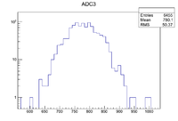
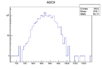
| Run # | Configuration | ADC3 | ADC9 |
| 4625 | Na-22 Source run with RF no beam current |  |

|
| run# | Mode and Energy | T1 | T2 | Sweep Magnet | D1 and D2 (Amp) | logic | HV NaI Left (CH3) (Det#1) | HV NaI R Right (CH9) (Det#2) | Dis Threshold Left | Dis Threshold Right | Reprate | start | stop | Run time (s) | Int Rate | comments | event | pulses |
| 4623 | 3 MeV e+ on T2 | in | in | out | 5.8, 5.8 | (NaIL & GunTrig) & (NaIR & GunTrig) | 1100V | 1190V | 5 mV | 5 mV | 300 | 16:43:26 | 16:: | events/s | beam pulses |
| Run # | Source | logic | Run starts | Run ends | HV NaI Left (CH3) (Det#1) | HV NaI R Right (CH9) (Det#2) | Spectrum | |
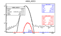
| 4624 | Na22 | NaI Right && NaI Left | 19:42:36 | 08:03:30 next day | 1100 V | 1190 V |
RF adds 50 channels of noise to NaI signal and moves Source peak forward.
RF was for 3 MeV electrons, perhaps RF for higher energy electrons will add the remaining 30 channels of noise on the NaI detectors.
Positron attempt
| Run # | Configuration | ADC3 | ADC9 |
| 4632 | Transporting 3 MeV positrons, Looks like beam right (ADC9) has 511s beam left (ADC3) swamped with photons | 200 px | 200 px |
Need to shield beam left more.
Scintillator and Quartz cabling
Changed the scintillator detector known as "Jenni" so its HV is controlled remotely through connector SHV59A7 and its signal is on connector 223A7.
Kelly is the scintillator on the accelerator side.
The quartz detector is on connector SHV59A8 and the signal on 223A8.
12/21/2012
| Run # | Configuration | ADC3 | ADC9 |
| 4648 | Transporting 3 MeV electrons, Trigger is OR with beam gate No TDC , T2 out | 200 px | 200 px |
| 4651 | Transporting 3 MeV positrons, TDC working now , T2 out , or between NAI | 200 px | 200 px |
| 4652 | Transporting 3 MeV positrons, TDC working now , T2 IN, T1 in , or between NaIs, ADC3 was 100 Volts too high for the above runs | 200 px | 200 px |
| 4653 | Transporting 3 MeV positrons, T2 IN, T1 in , or between NaIs, | 200 px | 200 px |
| 4653 | Transporting 3 MeV positrons, T2 IN, T1 in , or between NaIs,Lowered NaI HV by 100 VOlts | 200 px | 200 px |
NaI voltages
HV Left = 1100 V
Right = 1190 V
The ADC3 spectrum seemed to have a lot less photons, but then so did the ADC9 spectrum.
