2011
AFCRD Reports-2011
- A vendor is being sought for a flex circuit version of the readout card adapter in order to allow the readout cards to attach to the detector more easily.
- A detector gas system upgrade is underway and should be completed before the next quarter
- A new TGEM card has been machined which was redesigned to reduce spark discharge between two adjacent TGEM preamplifier cards previously observed at 1.7 kV. The expectation is to reach a TGEM voltage of 2 kV with two preamplifier cards stacked on top of each other and separated by 2.5 mm.
January
- Determined the closest distance between two TGEM amplifier cards at 2kV to be 2.5 cm.
- Readout card adapters have arrived
- A third TGEM amplifier has been fabricated
February
- A third THGEM card is installed, the detector is ready to test with cosmic rays.
- New flex circuit adapter cards have been stuffed with connectors. The 16 signals on five 20 pin connectors will be merged onto one 130 connector used by the digitization cards.
- New HV-circuit design is ready to give the needed voltage to operate three THGEM cards simultaneously with the cathode.
- A gas system is currently in place with a 50 micron filter and a flow meter. Check valves are being sought to support a system using 2 supply tanks for continuous operation. The check valves will allow an empty tank to be replaced while the gas system continues operating on a second tank.
Look for NE213 and NE230 liquid scintillator detectors for fast neutrons. Does the neutron leave the detector?
March
- The detector's cathode-TGEM distance had to be increased in order to avoid a spark discharge problem was found when testing the detector at HV using cosmic rays.
- A modification took place on the detector's cavity by raising up the detector's widow 5 cm which helped to increase the distance between the cards.
April
- A setback to the project occurred when a spark discharge event, during excessive testing, destroyed our 3 THGEM pre-amplifiers.
- Seven FR4 cards, coated with resistive paste, were submitted to the machine shop in ISU and they will be ready in the time after May 15.
May
- Two new THGEM cards and cathode have been installed in the THGEM detector. the card testing is going according to the procedure mentioned below.[[1]]
June
- Three THGEM cards were installed in the gas chamber, a procedure is taken for testing the cards to have the smallest gap between the THGEM cards without any discharge. The result, a group of 3 THGEM cards with an average voltage of 2.1kV are stacked together with a separation distance of 3.2mm without observing any discharge effect.
- The next step is adding the the cathode to 3 THGEM cards then trying to operate the detector.
1/13/11
- Sparking Test
Sparking test for the HT-THGEM of holes size(76) and rim (63)
| Separation distance (mm) | type of gas surrounding | V1GB (kV) | V1GT(kV) | V2GB (kV) | V2GT (kV) | Notes |
| 6.5 | Ar/CO2 | 0 | ||||
| 5.0 | Ar/CO2 | 0 | ||||
| 2.6 | Ar/CO2 | 0 | -2 | +2 | -3 | sparking on the edge then holes starts to spark too |
| 2.6 | Air/CO2 | 0 | -2 | -2 | 0 | no sparking. |
where:
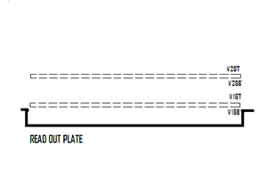
V1GB = bottom of the first THGEM card which is placed 2 mm above the charge collector
V1GT = top of the first THGEM card
V2GB = bottom of second THGEM card just above the first TGEM card.
V2GT = top of second THGEM card.
1/21/11
- The THGEM card is still sparking because of the hook up wires; which are tested up to 600V by the manufacturer.
The maximum voltage applied for one card only is 2000V on the top and 2000V on the bottom of the card. As soon as the voltage increases more than 2000V on the bottom of the card. a spark is seen in the hole that contains the hook up wire. There is an insulation problem may get serious specially if we still planning to apply 4kV and 6kV on the THGEM card.
The following website is offering hook up wires solid core and can hold up to 2000V, 24 gauge size.
http://caledonian-cables.com/product/Hoop-Up_Wire/UL_1430_Hoop-Up_Wire.htm
we may use the wires supported by the glu to have a good insulation.
- Next step is to repeat the experiment again but after adding the glu on the soldered parts.
2/14/11
- Leakage current test
On Thur. 2/10 the leakage current measured for the max. voltage (around 300V) was in 25 nA using user1 setup.
Today the measured current for the voltages shown in the table using user0 setup in clean environment:
| Source Voltage(V) | GEM Voltage (V) | Current (uA) | Notes |
| 500 | 196 | 6.1 | Sparking rate was high in the beginning, higher current observed in a higher sparking rate |
| 570 | 224 | 23 | GEM sparking rate decreased after a while, current most of the time in the range of the noise level |
Switching to user1 setup when the voltage applied 224V on GEM foil, the maximum current measured was around 10um. The result is not enough to compare the accuracy of the two setups, but it gives a feeling that user1 setup is underestimating.
- The 3rd THGEM card is ready to pick up, the vendor suggested to find another place to do the one with massive number of holes since this semester there is not any time available to do it.
I will start working to collect the 3 cards together using the high voltage circuit distribution, an adjust is going to take place to get the desired voltage for the 3 cards in addition to the cathode.
2/15/11
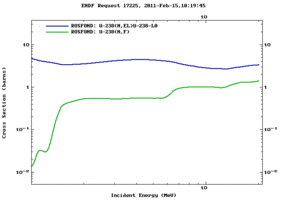
The following figure shows the elastic xsection and fission xsection for U-238:
The elastic scattering is higher over the energy range of 5-14 MeV, the probability for the U-238 to recoil is higher than that to have a fission.
2/17/11
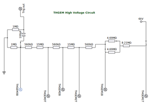
- The high voltage circuit is ready to get a voltage up to 9 kV from the source to provide a voltage up to 2 kV for each THGEM card and potential difference between successive cards up to 115 V (between the high voltage sides) and 80 V (between successive low voltage sides).
2/22/11
The operating voltage for the HV-circuit is 5kV, the voltages on the sides of the THGEM cards is as the following:
| Source Voltage(kV) | THGEM_T1 (kV) | THGEM_B1 (kV)Current (uA) | THGEM_T2 (kV)Notes | THGEM_B2 (kV) | THGEM_T3 (kV) | THGEM_B3 (kV) |
| 5.15 | 5.15 | 2.92 | 5.00 | 2.88 | 2.49 | 1.90 |
But in the case of connecting the two circuits together, the effect of the capacitor extends to the other circuit causing the difference in voltage between top and bottom of each THGEM cards is only 0.5kV.
3/10/11(HV_circuit)
- New design for HV-circuit
A new design is ready to feed the THGEM cards with voltage difference up to 2kV between the top and the bottom side of the card. Also source drops gradually according to that difference from 6 kV (operating voltage) to 0.1 on the bottom of the card which is closer to the read out card.
The follwing table shows the voltage distribution to the cards as the voltage source rises from 4 kV up to 6.5 kV.
| Voltage source (kV)+_ 0.01 | THEGM card number | Top side voltage(kV)+_ 0.01 | Bottom side voltage (kV)+_ 0.01 | Voltage difference between the two sides (kV)+_ 0.01 |
| 4.06 | 1 | 4.06 | 2.85 | 1.21 |
| 2 | 2.36 | 1.44 | 0.92 | |
| 3 | 1.38 | 0.08 | 1.3 | |
| 4.50 | 1 | 4.50 | 3.15 | 1.35 |
| 2 | 2.71 | 1.58 | 1.13 | |
| 3 | 1.54 | 0.08 | 1.46 | |
| 5.00 | 1 | 5.00 | 3.55 | 1.45 |
| 2 | 3.06 | 1.86 | 1.20 | |
| 3 | 1.80 | 0.11 | 1.69 | |
| 5.50 | 1 | 5.50 | 3.81 | 1.69 |
| 2 | 3.74 | 2.04 | 1.78 | |
| 3 | 1.98 | 0.12 | 1.86 | |
| 6.00 | 1 | 6.00 | 4.00 | 2.00 |
| 2 | 3.93 | 2.06 | 1.87 | |
| 3 | 2.00 | 0.23 | 1.77 | |
| 6.1 | 1 | 6.10 | 4.08 | 2.02 |
| 2 | 4.00 | 2.10 | 1.90 | |
| 3 | 2.04 | 0.23 | 1.81 | |
| 6.2 | 1 | 6.20 | 4.15 | 2.05 |
| 2 | 4.06 | 2.13 | 1.93 | |
| 3 | 2.07 | 0.24 | 1.83 | |
| 6.3 | 1 | 6.30 | 4.21 | 2.09 |
| 2 | 4.13 | 2.17 | 1.96 | |
| 3 | 2.11 | 0.24 | 1.87 | |
| 6.52 | 1 | 6.52 | 4.47 | 2.05 |
| 2 | 4.28 | 2.39 | 2.11 | |
| 3 | 2.33 | 0.14 | 2.15 |
THGEM card number 1 is the closest to the cathode. THGEM card number 3 is the closest to the readout card.
- When the voltage is 6 kV, the current that passes through the circuit is
3/18/11
- Sparking Cathode
The cathode is still sparking even when it is replaced by another new one with the same dimension and distance from the THGEM cards. when I tried to make a little higher I could not since the top part of the detector has less space to get the increment in height.
Machining the top part is important to get more distance for the cathode to avoid the sparking (minimum another 2 cm and if it is more it would be better).
if we succeed to get that space, then a longer corner screw can be installed to give us a little flexibility to get a better distance for the cathode as it is mounted vertically.
4/4/11
- The detector window's extension is completed and it is test, totally sealed without any gas leakage.
4/9/11
- The THGEM is tested to look for a signal, Na-22 and Co-60 sources were used for this purpose, the result that New kind of peaks were detected followed by a tail. Unfortunately the test did not reach the full voltage capacity (up to 6.5 kV) but it was operating under 4.5 kV.
- The detector was tested again before removing the cards without Ar/CO2 gas, the applied voltage on the cards was up to 2.5-2.7 kV, without any sparking, cathode was under 8 kV, without any sparks, I excluded the distance between the cards is small to cause a spark, otherwise I won't be able to reach that high voltage without any sparks.
- The detector was inspected after the test, signs of sparking were very clear on the THGEM, and they all located in the same side for the 3 cards but in different degrees of burns (the bottom one was he worst). Through the inspection I was wondering how can they all be burnt on the same side of the card ?????
4/13/11
- The detector was tested without the cathode, the maximum voltage was 6 kV without sparking, looks the distance should be increased to exclude it of being a reason for sparking and to hit 6.5 kV easily.
- The distance is increased to about 1 mm, the detector is tested again and we hit 6.3 kV as maximum voltage on the THGEM without the cathode.
4/14/11
- The distance between the THGEM is increased to another 1mm ( to have a total of 0.5 cm), the cathode is added to the group with a maximum distance from the top THGEM card, observation will uploaded as soon as possible.
4/18/11(HV-probe)
The following is a list of what is available in the markets:
This is what the IAC are using :
I think this is good for our our application , (the price with shipping = 119 + 7 +_ 1) :
5/26/11
There are new 6 THGEM cards machined and ready for installation.
- Steps of Installing the new THGEM cards
1- Cleaning the chamber under the laminar hood.
2- Cleaning the card very well by alcohol and be sure there is not any place on the surface that may collect charge.
3- Installing a card then performing the discharge test up to 2 kV.
4- whenever the card passes the discharge test another card will be added until 3 cards installed in the chamber.
5- Adding the cathode to an appropriate distance in a way the charged particle range is covered within this distance and there is not any discharge.
- Procedure for adding an alpha source film to the detector to test the detector signal???? Please add your comments.
- GEANT4 changes:
A discussion about the ENDF data used by GEANT4 9.4 that does not include Th-232 fission cross section, the collaborators recommended me to contact Tatsumi for more information about the Th-232 and U-238 cross sections . He sent me a files that I can install in GEANT4 ENDF directory, I ma going ot repeat the simulation again for U-238 target of thickness of 1 um to measure the to calculate the fission cross section. They also recommend me to contact the INCL model programmer and discuss with him the issue of underestimating the values of the fission cross section in our simulation.
I am going to start my simulation on BREMS using the new fission cross section file. Is that ok?
Summary or testing 3 THGEM cards with a distance of 7.5 mm without a cathode
- Table of observations
7/5/11
- The vertical distance between the THGEM card is 9 mm except for top one that follows the union, it has a distance of 11mm.
7/8/11
- The THGEM cards have insulating layers on both sides covering the copper frame, the separation distance is still as mentioned above (9mm and 11 mm after the union). The tests for the THGEM are represented by the following table:
Why aren't you able to have at least 4 measurements each day?
A: I do sometimes a test directly after the last test ends, I do not observe the reproducibility, which make me think I have to wait a little to get consistency in the tests' results,(the last two tests are only 3h apart! )
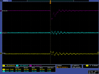
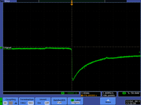
Also, a 2.5V noise detected in certain times and I can not avoid, and it trips the power supply.( for example, Sat. 7_9_11 appears frequently, oscilloscope picture is shown below).
The image above does not look like a spark
Perhaps your trip threshold is too low?
What voltage is your threshold set at?
A: at the time of the test was 0.4V. The maximum voltage by the discriminator is 1V.
Q: Will I be able to avoid it using the recent discriminator or I should have another one with a higher voltage threshold?
7/12/11
An attenuator is added to the circuit to decrease the amplitude any pulse detected to a fifth of the original value, the discriminator voltage is set to 0.5V so a discharge or a noise of >= 5V will trip the power supply.
The following table shows the new tests results with the new settings.
| Date and time | Time before HV trip | Voltage source | Current | Notes | discharge picture |
| 7/13/11_10:30-11:30am | 1h | 6.1 | 140 | No noise or discharge | |
| 7/13/11_11:35am-12:05pm | 0.5h | 6.2 | 143 | noise |
Can you detect a spark still?
I made the circuit in away that I can see the half spark before it is attenuated.
For the 2nd time I see the following noise tripping the power supply but I do not know why!!!
Perhaps the scope missed the spark signal that caused the trip?
I am thinking to install the cathode, should I? and I will keep working to improve the circuit to trip the voltage when it is 5 V or more.
No cathode Yet, we need the smallest distance between THGEMs which will hold 6.2 - 6 kV without sparking. I expect sparks to happen within an hour or less.
7/13/11
- The separation distance between the THGEM cards is 6.1mm including the one between the last THGEM and the readout plate. The gas will flow overnight at low rate to get the tests by tomorrow morning.
7/14/11
- Test results when the separation distance is 3.2mm.
| Date and time | Time before HV trip | Voltage source | Current | Notes |
| 7/14/11_5:50-6:50am | 1h | 6.0 | 139 | no discharge or noise, discriminator 0.25V |
| 7/14/11_6:54-7:54am | 1h | 6.2 | 144 | no discharge or noise |
| 7/14/11_8:01-9:12am | 1.1h | 6.5 | 151 | no discharge or noise |
7/18/11
- The cathode gap was 6.1 mm, there was not any signal from the detector when it was tested by the radioactive isotopes. The highest voltage I reached was 6.3 kV for the THGEM cards and 6.4 kV on the cathode, I heard the knocking sound again, I thought it was a spark that does not propagate through the trigger out but it was not.
- The cathode gap is 9.2 mm, the detector is free from any burns or signs of sparking. The detector will stay overnight under the gas to test it under the same environment tomorrow with the new distance.
7/20/11
The following is expected to be noise detected when the the the cathode voltage is 6.3kV and the THGEM source voltage is 6.1kV:
7/22/11
- A trial took place today to place an alpha source on the THGEM cathode, unfortunately the source is very fragile and easily breaks into small pieces that may spread inside the detector and causes contamination for any kind of motion for the detector's chamber, I removed everything from the cathode and I cleaned it very well.
7/25/11 (particle Counter user directions)
Clean Room Particle Counter User Directions
7/26/11 Installing Radium source
Counts Measurement
A "Radium C" source was installed. This is mostly Bismuth-209.
Using a Lund hand held survey meter Model 2401-P we observed a contact activity between 0.8 and 1.5 mR/hr (2500-5000 CPM), R stands for roentgen.
The detector efficiency is 35.2% (Cl-36), 74.8% (Sr-90), 3.0%( Am-241), 3.5% (C-14), 20.1% (Bi-210), 17.2% (Tc099).
This is the rate of beta particles.
The alpha rate is probably 5% of this rate.
ArC02 gas volume = 100 cm^3
7/27/11
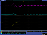
- The detector is tested as the new source is inside, the peak is observed when the voltage 4.8kV and 5.1kV on the THGEM and the cathode successively.The following pulses were observed:
- But when the voltage increased to 5.2kV and 5.5kV (THGEM and cathode) I got the pulse inverted!
- Another trial took place today to test the THGEM detector as a radioactive source is inside the gas chamber, the voltage went up to 6.3kV and 6kV that ended up with a spark that tripped the power supply. So, the maximum voltage for operating the detector without any discharge is 5.9kV and 6kV for the THGEM cards and the cathode successively.
oscilloscope compensation error message
7/29/11
New HV circuit
- A new high voltage circuit is installed by the following voltage characteristics:
1- Between The THGEM cards:
| 5.1 | 1.4 | 1.3 | 1.1 |
| 6.1 | 1.7 | 1.6 | 1.4 |
| 7.2 | 2.0 | 1.8 | 1.6 |
2- Relative to the ground:
| 5.1 | 5.10 | 2.46 | 2.43 | 1.19 | 1.17 | 0.07 |
| 6.1 | 6.1 | 2.96 | 2.93 | 1.43 | 1.40 | 0.08 |
| 7.2 | 7.2 | 3.49 | 3.45 | 1.69 | 1.66 | 0.09 |
- Three THGEM cards are installed with a separation distance of 3mm, resistive paste cathode is used instead of the copper cathode with a separation distance of 9.2mm but it is without the source. The chamber will be filled with Ar/ gas overnight to create an appropriate environment for a sparking testing which will be performed by next morning.
7/30/11 Table of sparking tests using the new HV circuit for 3 THGEM
- The sparking test was performed to test THGEM cards using the HV-circuit, the gas was blown to the chamber for 1h for each test except for the first 3tests. the aim is reach the minimum distance between the THGEM cards with a cathode far enough to cause any sparking.
8/19/11 Table of sparking tests using the new HV circuit for 4 THGEM
New HV circuit is installed in the THGEM detector setup, the follwing table shows the results of the testing the the new set up:
Card testing
| Date | No. of THGEM cards | THGEM cards distance (mm +_ 0.1) | Cathode is used | Cathode distance (mm +_ 0.1) | voltage (kV+_ 0.1) | Notes | spark picture |
| 8/24/11 | 1 | 0.0 | yes | 6.0mm | 2.2kV | card_D is stable, but there is not any signal detected using the alpha-source | |
| 8/25/11 | 1 | 0.0 | yes | 6.0mm | 2.2kV | card_B is stable, but there is not any signal detected using the alpha-source | |
| 8/29/11 | 2 | 3.0 | yes | 6.0mm | 4.2S | card_B isn ot stable, sparking starts at source voltage indicated which will provide the card approximately a voltage difference of 1.7kV |
8/31/11 THGEM as an alpha detector
An alpha source is installed by sticking the source on the center of the cathode. the source has unknown activity but it emits alpha and negative beta with a ratio of 1:6, the source has a vertical separation distance of magnitude of 3-6mm from the first THGEM card.
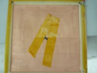
Pictures of mounted source Radium C
10/13/11 Detector Testing
- Two resistive paste THGEM cards were installed inside the Flex testing chamber, a readout plate is place in the bottom of the 2nd THGEM, a cathode is mounted at the top of the first. the vertical separation distance is the same for all and equal approximately to 2mm .
A 1 Hz signal is observed:
9/14/11
My research main goal is to measure the efficiency of Thick Gaseous Electron Multiplier Preamplifiers (THGEM) as a Neutron Sensitive Detector in the range of 1-14 MeV. The THGEM is constructed using an FR4 substrate that has been coated with a resistive paste. A staggered array of millimeter size holes are machined in the THGEM. The resistive paste is removed from the perimeter of the holes in order to reduce the spark discharge probability. The focus of my work is to dope the resistive paste with a neutron sensitive material. A determination of the neutron sensitive material type and optimal doping strategy to produces a high detection efficiency is the goal of my work.
TTL switch Power supply test circuit
- The circuit needs 12 resistors, such that as voltage applied is 2.5V, the circuit can hold up a current up to 100000 uA and minimum electric power of 0.5W ( assuming the value of each resistor is 2 ohm).
- A TTL switch is going to be used by using DG417 File:TTL switch DG417.pdf chip which has the following properties:
1- It has the following logic table:
2- TTL logic compatibility.
- NAND gate 2.8ns
- Digikey
| Logic Gate | minimum switching time (ns) | Part Number | weblink | minimum order | availability |
| NOT | 1 | TC7SET04FFCT-ND | http://search.digikey.com/scripts/DkSearch/dksus.dll?Detail&name=TC7SET04FFCT-ND | 1 | in stoke |
| NAND | 1.5 | TC74LCX00FNF-ND | http://search.digikey.com/scripts/DkSearch/dksus.dll?Detail&name=TC74LCX00FNF-ND | 1 | in stoke |
vendors
- dg417
http://search.digikey.com/scripts/DkSearch/dksus.dll?lang=en&site=US&KeyWords=maxim+dg417&x=0&y=0
- SHV Jack
http://www.pasternack.com/product-SHV-Jack-Bulkhead-Rear-Mount-Solder-Cup-Contact-PE4499-70717.html
Most vendors offer the SHV-connector with price between 18-25$
I can not find cheaper price than 18$, but the connector that is attached to testing chamber has cheaper price and available in stoke : http://www.ebay.com/sch/i.html?_from=R40&_trksid=p5197.m570.l1312&_nkw=SHV+connectors&_sacat=See-All-Categories
THGEM card Transparent test chamber
The transparent test chamber project is complete.
The chamber has a gas leakage of 0.4 SCFH (the gas system is well insulated to lower than 0.5 SCFH)
Verifying the new method of applying the paste
The eSEM pictures verified the desired thickness of the resistive paste on FR4 as shown the follwing table:
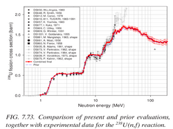
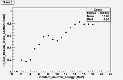
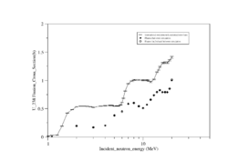
Comparison ENDF evaluation of U-238 neutron fission xsection and GEANT4
 |
 |
|
INTERNATIONAL EVALUATION OF NEUTRON CROSS-SECTION STANDARDS, INTERNATIONAL ATOMIC ENERGY AGENCY,VIENNA, 2007 File:U238-xsection.pdf
- absolute f_xsection in the table 7.1 p.91
| Ref. number | inxn | data description | author | citation | notes |
| 809 | 238U(n,f) | Absolute | G. Winkler et al. | 91Jülich (1991) 514 | the paper represents f_xsection ratio measurements of U_238 to Al_27, Na_24, Fe_56, Mn_56 * found in library QC770 N742 1992) |
| 810 | 238U(n,f) | Absolute | K. Merla et al. | 91Jülich (1991) 510 | * The paper represents f_xsection ratio measurements of U_238, U_235 , Np_237, and Pu_239 for 4.45 MeV, 8.46 MeV, 18.8 MeV * very accurate description for the experiment details and through the figures and the tables * found in library QC770 N742 1992) |
| 877 | 238U(n,f) | Absolute | I.M. Kuks et al. | At. Energy 30 (1971) 55 | *measured f_xsection U_238 fission for 2.5 MeV Neutrons |
| 860 | 238U(n,f) | Absolute | N.N. Flerov et al. | At. Energy 5 (1958) 657 | *title : antinutrino , Mean number of neutrons emitted in fission of U235 and U238 by 14-Mev neutrons, Mean number of neutrons emitted in fission of U235 and U238 by 14-Mev neutrons |
Done In April (edited by 04/30/10)
1.)Testing the new laminate with random holes after applying the resistive paste on both sides. Also, the trial of applying the paste was done, 0.1 inch brush is used for that to avoid covering the holes with the paste. the following procedure were taken:
a- Voltage is applied on the the foil to check the first sparking place.
b- Applying the paste carefully on the area between the holes with very small quantities.
- Result
a) Applying the paste shifts the sparking area to next neighboring one, so looks this will lead us to cover all the areas between the holes to kill the sparks.
b)A need to keep the foil under voltage to keep tracking of the sparks which lead unfortunately led to loss the voltage between the two copper layers.
Even a drop of paste got stuck in one of the holes(which has low possibility since I cleaned all the paste applied very well), or the two layers are no longer isolated from each other!
2.)Final touches on the HV-circuit are done, diagrams are done by eagle with Gerber files, the chamber is ready for redesigning.
3.)Running Th-232 fission simulation without ionization on inca and daq1. Energies 1-9MeV (inca) and 19-22 MeV(daq1) will be done by today(04/30/10).
4.)Tracking the process to get Th-232, contacting other vendors for radioactive isotopes, trying to get low cost ones.
Th-232 and U-238 Activity in mCi
General information:
| Physical properties | U-238 | Th-232 |
| Half life in years | 4.468 X 10^9 | 1.405 X 10^10 |
| Decay rate per second | 4.91 X 10^-18 | 1.56 X 10^ -18 |
| Molar Mass g/mol | 238.02891 | 232.0381 |
| Activity of 2 kg in mCi | 0.68 | 0.22 |
Avogadro's number is 6.0221 X 10^23 /mol
1 Ci = 3.7 X 10^10 disintegration/ second
