PePPO NaI PositronDetector 4 JLab
Detector setup for a NaI positron detector for PePPO
NaI detector
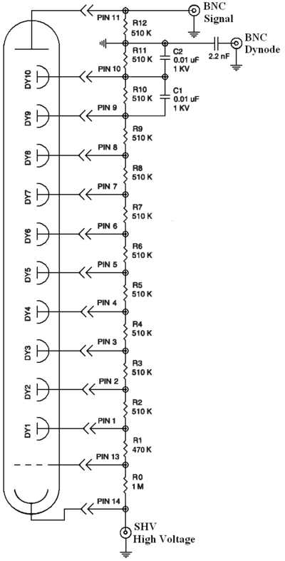
The PMT is powered by a HV supply which should have a DC ripple less than 200 mV peak-to-peak at 3kV/3mA. A DC ripple will change the gain of the PMT and cause the energy resolution to deteriorate.
The Linearity of the detector system is another way to reduce the energy resolution. The measured PMT output should be linear with the input signal when the gain is constant. This linearity can be measured using 2 radiation sources.
Input HV: +1085 V
Input Current: 2.362 mA
Running CODA: Running CODA
Measurements Using V792 QDC
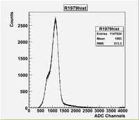
Run 1979
Start Time : March 23:12:30:26
End Time: March 23: 13:10:47
Elapsed time: 2421 seconds
Run 1980
Remove Na-22 source from top of NaI crystal.
Start Time : March 23:13:11:23
End Time: March 23: 15:56:40
Elapsed Time:6317 seconds
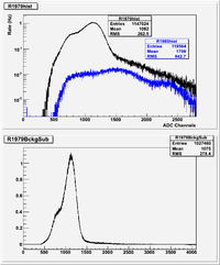
Let's lower the gain of the Phillips 777 amplifier so the 511 peak is around channel 500. This way the 1 MeV photons may come on scale.
Run 1982
Overnight Cosmic Run
Start Time : March 23: 16:01:47
End Time: March 24: 09:41:31
Elapsed Time:63558 seconds
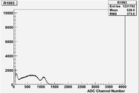
Run 1983
Start a run using Co-60
Start Time : March 24: 09:46:25
End Time: March 24: 10:14:24
Elapsed Time: 1679 seconds
The 1.x MeV gammas appear near channel 1200.
I'll do a long Na-22 run and think about upping the amplifier gain again to put the Co-60 peak around channel 3000.
The Co-60 source trigger rate is about 750 Hz and the Na-22 trigger rate was about 450 Hz.
Run 1984
Start a run using Na-22
Start Time : March 24: 10:16:49
End Time: March 24: 11:02:38
Elapsed Time: seconds
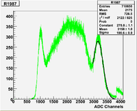
Run 1987
Increase gain of Phillips 777 amplifier which
I am using on the PMT output,  We may want to adjust
the dynode gain/discriminator to fill in the lower
energy part of the spectrum.
Start a run using Na-22
Start Time : March 24: 11:34:35
End Time: March 24: 1 Elapsed Time: seconds
I was expecting to see a photon of energy 1.17 and one with 1.33 MeV in the above specturm. Assuming that my ability to resolve the two peaks is due to noise I will assume both are in the peak at channel . Since the intensity of the above two lines are almost the same I will do a simple average.
- MeV
The above measurement indicates that a 1.25 MeV photon appears at channel in the current apparatus.
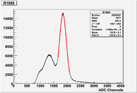
Run 1988
Start a run using Na-22
Start Time : March 24: 11:34:35
End Time: March 24: 16:21:31
Elapsed Time: 17216 seconds
The above measurement indicates that a 0.511 MeV photon appears at channel in the current apparatus.
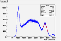
Run 1989
Start a run using Co-60
Start Time : March 24: 16:23:30
End Time: March 24: 16:57:00
Elapsed Time: 2010 seconds
The above measurement indicates that a 1.25 MeV photon appears at channel previously it was at in the current apparatus.
The 98 channel difference is beyond the fit statistic.
Taking the average of the two give 3207 Channels.
Energy Calibration using run 1987-1989
Summary of Apparatus Specs
JLab PMT at +1185 Volts, 2.6 mA.
Dynode is inverted by Ortec 474 timing filter amplifier set to unity gain. The Ortec output is put through a Lecroy Model 4608C discriminator set to -44.8 mV.
Anode is amplified by a Phillips 777 fast Amp. Gained measured to be XXXXX
Doing a Linear fit using the two points
1.25 MeV ,3207 Channels
0.511 MeV , 1839 Channles
gives
Channels = 893.06 + 1851.2 MeV
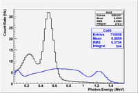
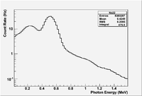
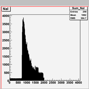
The energy distributions measured do not appear to have the expected structure. There is a 1.3 MeV energy gamma from the Na-22 source which was expected but only hinted at. Its intensity is 10% but it should start to show up on long runs.
The next goal will be to lower the dynode discriminator threshold so we trigger on lower energy events. Does the Compton edge become more obvious for Na-22?
I think my trigger threshold on the dynode is cutting things off at 200 keV.
Run 1990
Overnight Cosmic run
Start Time : March 24: 17:22:38
End Time: March 25: 09:14:44
Elapsed Time: seconds
Gain
Amplifier gain measurement for runs 1987-1989 using a 1.5 Volt battery
Changed integrate pulse width to 43 nsec
Run 1992: Battery going directly into ADC appear near channel 523
Run 1993: had battery through amp but forgot to plug in ADC, I'll take another run so interpretation is simple.
Run 1994: 1.5 Volt battery going into amplifier then ADC appears near channel 2190
so gain is 2188/523 = 4.18
Maybe I can increase the HV on the PMT to run without an amplifier and reduce my noise.
run 1995 Co-60 no amp
No Amplifier
Start a run using Co-60
Start Time : March 25: 09:46:23
End Time: March 25: 10:23:45
Elapsed Time: seconds
run 1996 Na-22 no amp
No Amplifier
Start a run using Na-22
Start Time : March 25: 10:26:43
End Time: March 25: 14:42:19
Elapsed Time: seconds
run 1997 Na-22 no amp
Increase HV on PMT from 1185 to 1250 Volts
Start a run using Na-22
Start Time : March 25: 14:43:55
End Time: March 25: 14:58:04
Elapsed Time: seconds
run 1998 Co-60 no amp
Increase HV on PMT from 1185 to 1250 Volts
Start a run using Co-60
Start Time : March 25: 15:09:30
End Time: March 25:
Elapsed Time: seconds
Rate was 5kHz and the ROC crashed
Move source farther away to lower rate
run 2000 Co-60 no amp
Increase HV on PMT from 1185 to 1250 Volts, 2.74 mA

Source moved 7.5 cm away from NaI to lower counting rate.
Start a run using Co-60
Start Time : March 25: 15:20:29
End Time: March 25: 15:26:54
Elapsed Time: seconds
run 2001 Na-22 no amp
Increase HV on PMT from 1185 to 1250 Volts, 2.74 mA

Source moved 7.5 cm away from NaI to lower counting rate.
Start a run using Na-22
Start Time : March 25: 15:28:13
End Time: March 25: 15:33:00
Elapsed Time: seconds
run 2002 Na-22 no amp
Increase HV on PMT from 1250 to 1350 Volts, 2.96 mA

Source moved 7.5 cm away from NaI to lower counting rate.
Start a run using Na-22
Start Time : March 25: 15:34:50
End Time: March 25: 15:38:54
Elapsed Time: seconds
run 2003 Co-60 no amp
Increase HV on PMT from 1250 to 1350 Volts, 2.96 mA

Source moved 7.5 cm away from NaI to lower counting rate.
Start a run using Co-60
Start Time : March 25:
End Time: March 25:
Elapsed Time: seconds
run 2004 Na-22 no amp
Increase HV on PMT from 1350 to 1430 Volts, 3.1 mA

Source moved 7.5 cm away from NaI to lower counting rate.
Start a run using Na-22
Start Time : March 25: 15:46:23
End Time: March 25: 15:52:06
Elapsed Time: seconds
- Looks like I was running at too low of a HV, that is why the spectra did not make sense above, I now see 2 peaks for Co-60 that are close together. What were those high energy peaks? Lets check the counting rate.
run 2005 Co-60 no amp
Increase HV on PMT from 1350 to 1430 Volts, 3.1 mA

Source moved 10.1 cm away from NaI to lower counting rate.
Start a run using Co-60
Start Time : March 25: 15:53:05
End Time: March 25: 16:03:24
Elapsed Time: 559 seconds
run 2006 Na-22 no amp
Increase HV on PMT from 1350 to 1430 Volts, 3.1 mA

Source moved 10.1 cm away from NaI to lower counting rate.
Start a run using Na-22
Start Time : March 25: 16:04:16
End Time: March 25: 16:24:04
Elapsed Time: 1188 seconds
- Channel = -540.15 + 1279.2 HeV
It looks like we should run the JLab tube at 1430 volts if we don't use an amplifier (tube is rated to 1500 Volts)
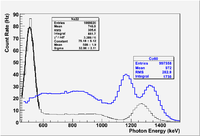
You see 4 peaks.
The Na-22 peaks at 511 keV and 1275 keV. A gaussian fit yields a sigma 36.5 for the 511 keV peak and 57 for the 1275 keV peak. The Co-60 source has two peaks. One at 1173 keV which has a sigma of 64.1 and one at 1332.5 which has a sigma of 61.23
= 7%, 4.4 %, 5.4 %, ,4.5%
The energy resolution at 511 keV is probably skewed because the discriminator threshold is low.
Linearity
Conclusions
It looks like we should run the JLab tube at 1430 volts if we don't use an amplifier (tube is rated to 1500 Volts) .
Readout
F250
JLab's F250 flash ADC will be used to measure the NaI output
ADdress is
| Address | ||
| Pin | Switch | bit |
| A12 | on/closed | 0 |
| A13 | on | 0 |
| A14 | on | 0 |
| A15 | on | 0 |
| A16 | on | 0 |
| A17 | off/open | 1 |
| A18 | off | 1 |
| A19 | off | 1 |
| A20 | on | 0 |
| A21 | off | 1 |
| A22 | off | 1 |
| A23 | off | 1 |
Module address = 0xee0000 = 111011100000000000000000 d
If I want 0xaa0000 = 101010100000000000000000 d
Setting FADC to bb address
If I want set 0xbb in hexadecimal, the binary will be 10111011
On the board:
on  = closed = 0
off = open   = 1
| Address | ||
| Pin | Switch | bit |
| A12 | on/closed | 0 |
| A13 | on | 0 |
| A14 | on | 0 |
| A15 | on | 0 |
| A16 | off | 1 |
| A17 | off/open | 1 |
| A18 | on | 0 |
| A19 | off | 1 |
| A20 | off | 1 |
| A21 | off | 1 |
| A22 | on | 0 |
| A23 | off | 1 |
I set it like above, but it didn't work at first. Then Dr. Forest turned roc1 off, and pushed the FADC in to the slot. He said it might be that the FADC did not sit well on the slot, so we need to push it.
I turned roc1 on, but it won't connect. It gives error says
telnet: connect to address 10.1.1.2: No route to host
I restarted roc1 several times, finally it worked. Was the error due to roc1 was not started?
Following is the message I got then
Starting FADC
Connect to roc1
telnet roc1
Trying 10.1.1.2...
Connected to roc1.
Escape character is '^]'.
Load FADC Libraray
-> ld < fadcLib.o
Undefined symbol: sysVmeDmaSend (binding 1 type 0)
Undefined symbol: sysVmeDmaDone (binding 1 type 0)
ld error: Module contains undefined symbol(s) and may be unusable.
value = 0 = 0x0
Initialize FADC
Recall that Address of ADC was set to be 0xbb0000
-> faInit (0xbb0000)
Initialized FADC 0  Slot # 4 at address 0x90bb0000
faInit: Enabling FADC Internal Clock, and Software Triggers (Soft Sync Reset)
value = 0 = 0x0
I think the address I set worked. But why it initialized at 0x90bb0000, instead of 0xbb0000? Is it because software set it 32 bit address?
Check Status
-> faStatus(0)
Software Triggering
https://wiki.iac.isu.edu/index.php/JLab_F250ADC#Software_Trigger
Hardware Triggering
https://wiki.iac.isu.edu/index.php/JLab_F250ADC#Hardware_Trigger
Na-22 source
North American Scientific Model CAL2600
Activity = 9.803 \muCi on 5/1/05
Serial Number 64236
Na-22 beta decays giving off a 215 keV KE beta and a 1.275 MeV photon.
http://atom.kaeri.re.kr/cgi-bin/decay?Na-22%20EC
Co-60 source
North American Scientific Model CAL2600
Activity = 9.641 \muCi on 5/1/05
Serial Number 64120
Co-60: decays to Ni giving 2 dominant gamma lines at 1.173237( 4) and
1.332501( 5) MeV. The Average Beta energy is 95 keV.
Co-60DecayChain.png
http://atom.kaeri.re.kr/cgi-bin/decay?Co-60%20B-
Detectors Documentations
SCIONIX HOLLAND
This is a Crystal with base.
Ruggedized Detectors:
http://www.helgesonsa.es/m02/firmas/SCIONIX/pages/pdf/Ruggedized%20Detector.pdf
LaCl 3:Ce Scintillation Crystals:
http://www.helgesonsa.es/m02/firmas/SCIONIX/pages/pdf/LaCl3%20literature.pdf
File:SCIONIX HOLLAND Crystal info.pdf
Rexon Components Inc
Voltage range: 0 - 2000 V DC (positive)
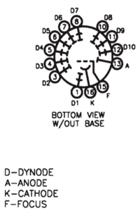
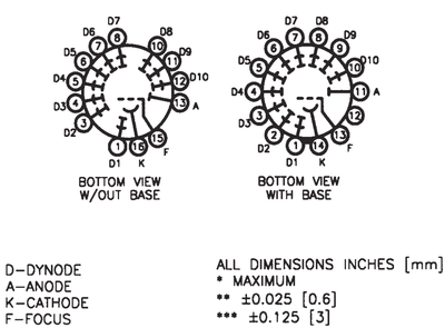
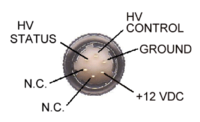
B76D01 PMT Pinouts
This is a Crystal, and there is a base from same company.
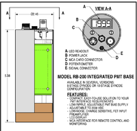
Rexon PB200 Base
Base: http://www.rexon.com/POWER%20SUPPLY2.htm
File:Rexon Base RB200datasheet.pdf
File:Rexon Base RB-200 PMT Base Manual.pdf
PMT:
size: 3" diameter
Saint-Gobain crystals & detectors ltd
This is just a base.
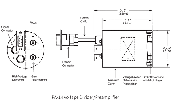
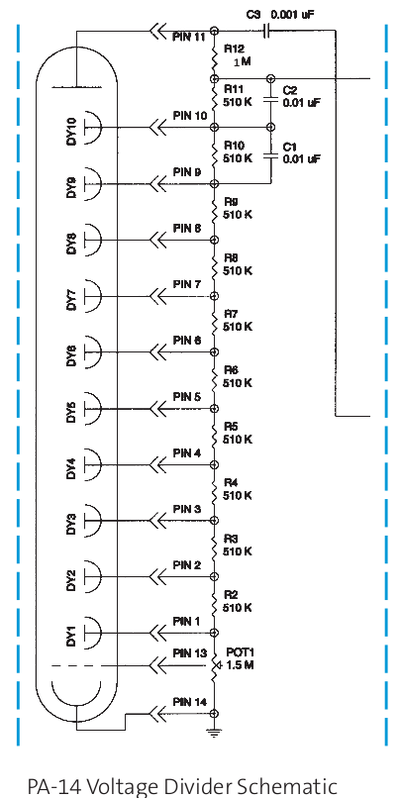
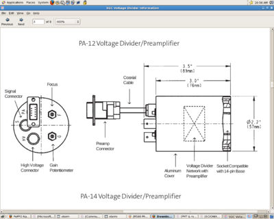
PA-14
Standard Features of Model P-14 Plug-on Voltage Divider
• Aluminum housing
• Positive (+) high voltage operation
• BNC bulkhead connector for signal output
• SHV bulkhead connector for high-voltage supply input
• 800 to 1200 VDC (may be higher or lower depending upon the specific PMT) at <1 mA typical operating power requirements
• Gain potentiometer
• Focus potentiometer
Additional features for model PA-14 plug-on voltage divider/preamplifier
• Standard hard-wired preamplifier power cable terminating in a 9-pin connector (pin 6 for -24VDC, pin 1 common ground)
• Optional BNC (in place of standard 9-pin) connector for preamplifier power input; -24V at 21mA operating power requirements.
Preamplifier specifications
• Noise: Less than 50 microvolts RMS referred to input
• Input: Directly coupled via 1μF capacitor from photomultiplier tube anode to charge integrating preamplifier input circuit, positive pulse output.
• Conversion Gain: 100mV/picocoulomb
• Rise Time: 100 nanoseconds
• Decay Time: 10 microseconds (internally adjustable at the factory)
• Gain Stability: 0.25%/C from 0° to 50°C
• Linearity: 0.25% (preamplifier only)
• Power Requirements: -24V +10% @21mA
Canberra Industries Inc.
This is just a base.
It is not clear from the PMT base we have what model is it, the data got scratched off. The comparison to information given on their website, it seems that the model is: 2007P.
http://www.canberra.com/pdf/Products/Model-2007-2007P-SS-CSP0071.pdf
Detectors Test
We got some other PMT from IAC. We applied Rexon base on these PMT, and tested them.
We put Co-60 source with S/N 67415. I think this source has activity less than 1 micro Currie (may be around 900 nano Currie).
I Applied 700 V to Rexon base. 1440 IAC
IAC IA-1377 SN6002-8292-I_blue_at700V_Co60Source67415_and_JLab_green_at1440V_Detectors
Saint_Gobain
 Model  Crystal Size   PMT Size
 3MW3/3   3” x 3”          3”
May Tests
You should turn on the JLab PMT to the HV we used last time (1420?) and take date with the Co-60 and Na-22 sources.
A replay program is in the directory below.
/home/daq/CODA/CODAreader/UsingROOTnEVIO/FADC/Mode1_Raw
Mode1_Raw >hsimple -fr2092.dat
JLab NaI Detector
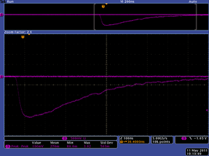
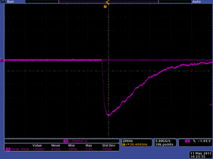
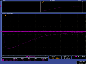
Cosmic ray scope images:
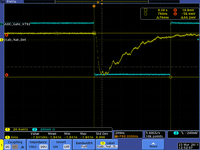
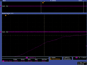
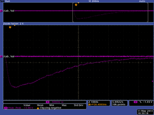
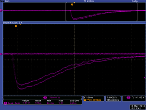
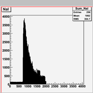
Cosmic ray images from Flash-ADC output
