TF EIMLab8 Writeup
Lab 8 The Diode Objective: Measure the current-voltage curve of a silicon diode.
Reverse current
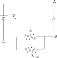
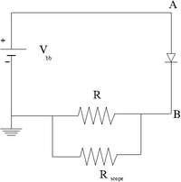
1.) Construct the circuit below using a DC power supply, a diode.
2.) attach an Oscilloscope set to 1M input impedence so the probe is located at point B. The oscilloscope's internal resistance will serve as a Resistor (R) to measure the voltage across the diode and calculate the current.
3.) Calculate the value of R needed to observe the current without burning up the diode. What is the max reverse voltage you will have.
P_{diode} = 0.5 Watts
V_{max} = 4.9 Volts
I_{rev}^{max} = 5 \mu A at V = 2 Volts
R = \frac{4.9}{5 \mu V} = 1 k\Omega
P = V I = 4.9 Volts \times 5 \mu A = 0.025 Wats
4.) Measure the diode reverse current as a function of the DC supply voltage. (30 pnts)
IN5230-B-T (4.7 Volt Zener Diode), The other diode is the IN5238B
Data sheet =>File:IN5230-B-T DataSheet.pdf
| V_Z | Z_Z (I_Z) | I_R (V_R) | Max Power |
| 4.7 | 19\Omega (20 mA) | 2\mu A (1 Volt) | 500 mW |
| Bias Volts | V_{scope} (1 M\Omega)(mV) | Current (V/R) | Power |
| -2.5\pm 0.05 | 5 \pm 7 | 5/50 = 0 \pm 0.02 mA | |
| -4.4\pm 0.05 | 59\pm 10 mV | 0.59 \pm 0.1 mA | |
| -4.70 \pm 0.05 | 220 \pm 10 mV | 2.2 \pm 0.1 mA | 449 mW |
| -5.03 \pm 0.05 | 1050 \pm 15 | 10.5 \pm 0.2 mA | |
| -5.22 \pm 0.05 | 2280 \pm 50 | 22.8 \pm 0.5 mA | too much power |
| Bias Volts | V_{scope} (1 M\Omega)(mV) | Current (V/R) | Power |
| 2.50 \pm 0.05 | 24 \pm 1 | 24/50 = 0.5 \pm 0.02 mA | 125 |
| 3.14 \pm 0.05 | 31.1 \pm 2 | 0.62 \pm 0.064 mA | |
| 4.07\pm 0.05 | 109 \pm 03 mV | 2.18 \pm 0.06 mA | |
| 4.46 \pm 0.05 | 274 \pm 3 mV | 5.4 \pm 0.06 mA | |
| 4.74 \pm 0.05 | 824 \pm 10 mV | 16.48 \pm 0.2 mA | 449 mW |
| 4.89 \pm 0.05 | 1860 \pm 10 | 37.2 \pm 0.2 mA | |
| 5.02 \pm 0.05 | 3880 \pm 10 | 77.6 \pm 0.2 mA |
| Bias Volts | V_{scope} (1 M\Omega)(mV) | Keithley ammeter |
| 0.6 \pm 0.001 | 2 \pm 1 | 1.24 \pm 0.01 |
| 0.9 \pm 0.001 | 10 \pm 1 | 8.69 \pm 0.01 nA |
| 1.05 \pm 0.005 | 22 \pm 0.5 mV | 24.3 \pm 0.05 nA |
| 1.16 \pm 0.005 | 40 \pm 1 mV | 49.4 \pm 0.05 nA |
| 1.23 \pm 0.005 | 56 \pm 1 mV | 78.6 \pm 0.05 nA |
| 1.27\pm 0.005 | 68 \pm 1 mV | 98.2 \pm 0.005 nA |
| 1.30\pm 0.005 | 75 \pm 1 | 118.2 \pm 0.5 |
| 1.35 \pm 0.005 | 93 \pm 1 | 158.2 \pm 0.5 |
| 1.4 \pm 0.005 | 112 \pm 1 | 213.0 \pm 0.1 |
| 1.45 \pm 0.005 | 132 \pm 1 | 279.1 \pm 0.1 nA |
| 1.50 \pm 0.005 | 155 \pm 1 | 366 \pm 0.5 nA |
| 1.55 \pm 0.005 | 182 \pm 1 | 474 \pm 0.5 |
| 2.53 \pm 0.01 | 902 \pm 4 | 24 \pm .5 \times 10^{3} nA |
| 2.95 \pm 0.05 | 290 \pm 9 | 10 \pm 1 \times 10^{4} nA |
| 3.85 \pm 0.05 | 2240 \pm 20 | 83 \pm 1 \times 10^{4} |
| 4.62\pm 0.05 | 2900 \pm 6 | 8.0 \pm 0.5 \times 10^{6} |
| 5.5 \pm 0.05 | 3740 \pm 30 | NA |
| 6.4 \pm 0.05 | 4760 \pm 23 | |
| 7.4 \pm 0.05 | 5700 \pm 33 | |
| 9.84 \pm 0.05 | 8.04 \pm 30 |
4.) Fill in the blank. The reverse biased diode act as a constant _______________ source. (5 pnts)
Forward Current
- now swap the diode direction and repeat the measurement in the previous section.
IN5230-B-T (4.7 Volt Zener Diode)
| Bias Volts | V_{scope} (1 M\Omega)(mV) | Keithley ammeter |
| 0.922 \pm 0.005 | 1780 \pm 40 | 17.80 \pm 0.4 mA |
| 0.953 \pm 0.005 | 2800 \pm 40 | 28.0 \pm 0.4 |
| 1.00 \pm 0.005 | 4280\pm 50 | 42.8 \pm 0.5 |
| Bias Volts | V_{scope} (1 M\Omega)(mV) | Keithley ammeter |
| 0.850 \pm 0.005 | 1740 \pm 20 | 1740/50 = 34.8 mA |
| 0.872 \pm 0.005 | 3090 \pm 20 | |
| 0.883 \pm 0.005 | 4230\pm 35 | |
Graph
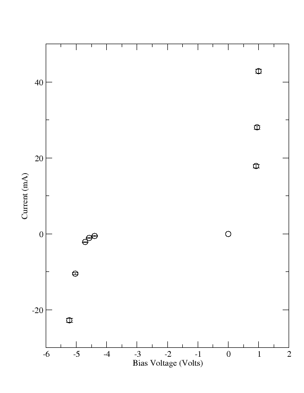
- Plot the diode current (on the ordinate) versus the diode voltage (on the abscissa)for both the reverse and forward bias measurements. (50 pnts)
Questions
1.) Plot the reverse biased diode for voltages beyond the turn on voltage and measure the effective impedance of the diode using a linear fit. (20 pnts)
2.)The measured reverse biased turn on voltage is _________ Volts for silicon diode type # IN_____________. The % difference between the measured turn on voltage and the one given in the specification is __________%. Circle the correct answer in the parentheses. This % difference (is / is not) within the measurement uncertainty. ( 10 pnts)
3.) Plot the forward biased diode and measure the effective impedance of the diode using a linear fit in the linear region at large bias voltages. ( 20 pnts)
Old question
- The reverse biased diode acts like a constant _____DC Voltage_______. (10 pnts)
- The forward biased diode has a very __________ resistance. A reverse biased diode has a very ____________ resistance.(10 pnts)
- The approximate DC forward resistance for diode #___________ is _________ when the forward current is _______________.(10 pnts)
- The approximate DC reverse resistance for diode #___________ is _________ when the forward current is _______________.(10 pnts)
- The silicon diode #___________ has an approximate turn on voltage of ___________.(10 pnts)


