Go Back to All Lab Reports
Lab 10 Unregulated power supply
Use a transformer for the experiment.
here is a description of the transformer.
File:TF EIM 241 transformer.pdf
File:IN5230-B-T DataSheet.pdf
Half-Wave Rectifier Circuit
1.)Consider building circuit below.
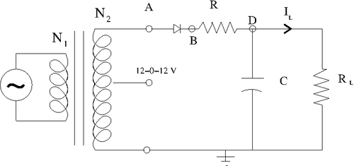
Determine the components needed in order to make the output ripple have a [math]\Delta V[/math] less than 1 Volt.
The output ripple can be found by [math]\Delta V=\frac{I\Delta t}{C}[/math]
Taking AC signal from outlet equals to [math]60\ Hz[/math] my input pulse width is [math]\Delta t = \frac{1}{60\ sec} = 17\ ms[/math] and using say [math]C = 2.2\ uF[/math] I need my current to be:
[math]I \le \frac{1\ V \cdot 2.2\ uF}{17\ ms} \le 0.129\ mA[/math]
Taking [math]R \ge 100\ k\Omega \Rightarrow I = \frac{12\ V}{100\ k\Omega} \le 0.12\ mA[/math]
that satisfy the condition above for current so my output ripple becomes less than 1 Volts.
List the components below and show your instructor the output observed on the scope and sketch it below.
I have used the following components:
[math]R = 96.9\ k\Omega[/math]
[math]R_L = 98.7\ k\Omega[/math]
[math]R_{scope} = 1\ M\Omega[/math]
[math]C = 2.2\ uF[/math]
[math]\mbox{Zener}\ \mbox{Diode}\ 4.7\ V[/math]
and the following input parameters:
[math]\Delta t = 17\ ms[/math]
[math]V_{in} = 12\ V[/math]
The current through the circuit can be found as [math]I = \frac{V_{in}}{R_{tot}}[/math]
where [math] R_{tot} = R + \left|\frac{R_L \cdot \frac{1}{j\omega C}}{R_L + \frac{1}{j\omega C}} \right| = R + \sqrt{ \left(\frac{R_L}{1 + j\omega CR_L}\right)\left(\frac{R_L}{1 + j\omega CR_L}\right)^* } = R + \sqrt{ \left(\frac{R_L^2}{1 + (\omega CR_L)^2}\right) } [/math]
[math] = 96.9\ k\Omega + \sqrt{\frac{(98.7\ k\Omega)^2 }{1 + (2\pi\ 60\ sec^{-1})^2(2.2\ uF)^2 (98.7\ k\Omega)^2} }= 96.9\ k\Omega + 1.2\ k\Omega =98.1\ k\Omega[/math].
And the current becomes [math]I = \frac{12\ V}{98.1\ k\Omega} = 0.122\ mA[/math]
So my output ripple becomes [math]\Delta V = \frac{0.122\ mA \cdot 17\ ms}{2.2\ uF} = 0.9 V[/math]

As we can see from the sketch above my output voltage has ripple about [math]\Delta V = 0.710\ V\lt math\gt , ripple time is the same as input time \lt math\gt \Delta t = 16.6\ ms[/math], and the output DC voltage is about [math]V_{out} = 0.6\ V[/math]
Full-Wave Rectifier Circuit
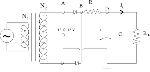
Determine the components needed in order to make the above circuit's output ripple have a [math]\Delta V[/math] less than 0.5 Volt.
The output ripple in this case can be found by [math]\Delta V=\frac{I (\Delta t/2)}{C}[/math]
Because we are now using [math](\Delta t/2)[/math] instead of [math](\Delta t)[/math] than in previous case for half-wave rectifier theoretiacally we will be able to make [math]\Delta V[/math] two times less then in previous case just by using exactly the same ellements and input parameters as before:
List the components below and show your instructor the output observed on the scope and sketch it below.
I have used the following components:
[math]R = 96.9\ k\Omega[/math]
[math]R_L = 98.7\ k\Omega[/math]
[math]R_{scope} = 1\ M\Omega[/math]
[math]C = 2.2\ uF[/math]
[math]2\ \mbox{Zener}\ \mbox{Diode}\ 4.7\ V[/math]
and the following input parameters:
[math]\Delta t = 17\ ms[/math]
[math]V_{in} = 12\ V[/math]
Because now I need to replace [math]\Delta t[/math] by [math](\Delta t)/2[/math] my output voltage now becomes two times less:
[math]\Delta V = \frac{0.9\ V}{2} = 0.45\ V[/math]
Go Back to All Lab Reports Forest_Electronic_Instrumentation_and_Measurement


