Lab 10 RS
Lab 10 Unregulated power supply
Use a transformer for the experiment.
here is a description of the transformer.
File:TF EIM 241 transformer.pdf
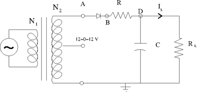
Half-Wave Rectifier Circuit
1.)Consider building circuit below.
Determine the components needed in order to make the output ripple have a less than 1 Volt.
The output ripple can be found by
I have used the following components:
List the components below and show your instructor the output observed on the scope and sketch it below.
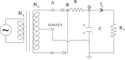
Full-Wave Rectifier Circuit
Determine the components needed in order to make the above circuit's output ripple have a less than 0.5 Volt.
List the components below and show your instructor the output observed on the scope and sketch it below.
Go Back to All Lab Reports Forest_Electronic_Instrumentation_and_Measurement

