gain
Loop Theorem
- [math]\Rightarrow V= I(R+X_{tot}) = I \left (R+ \frac{i \omega L}{1- \frac{\omega^2}{\omega_{LC}^2}} \right )[/math]
or
- [math] I= \frac{V_0 e^{i \omega t}}{\left (R+ \frac{i \omega L}{1- \frac{\omega^2}{\omega_{LC}^2}} \right )}[/math]
- Notice
- When [math]\omega \approx \omega_{LC} = \sqrt{\frac{1}{LC}}[/math] then the AC signal is attenuated.
Looking at the Voltage divider aspect of the circuit
- [math]V_{AB}=V_{out} = \frac{X_{tot} }{R + X_{tot}}V_{in}[/math]
- [math]\left |\frac{ V_{out}} {V_{in}}\right | = \sqrt{ \left [ \frac{X_{tot} }{R + X_{tot}} \right ] \left [ \frac{X_{tot} }{R + X_{tot}} \right ]^*}[/math]
- [math] = \sqrt{ \left [ \frac{\frac{i \omega L}{1- \frac{\omega^2}{\omega_{LC}^2}} }{\left (R+ \frac{i \omega L}{1- \frac{\omega^2}{\omega_{LC}^2}} \right )} \right ] \left [ \frac{\frac{i \omega L}{1- \frac{\omega^2}{\omega_{LC}^2}} }{\left (R+ \frac{i \omega L}{1- \frac{\omega^2}{\omega_{LC}^2}} \right )} \right ]^*}[/math]
- [math] = \sqrt{ \frac{ \omega^2 L^2 \omega_{LC}^4}{R^2(\omega_{LC}^2 - \omega^2)^2 - \omega^2L^2 \omega_{LC}^4}}[/math]
- [math] = \sqrt{ \frac{ \omega^2 }{C^2R^2(\omega_{LC}^2 - \omega^2)^2 - \omega^2}}[/math]
- [math] = \sqrt{ \frac{ \omega^2 }{\frac{1}{\omega_{RC}^2}(\omega_{LC}^2 - \omega^2)^2 - \omega^2}}[/math]
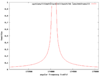
| [math]L = 33 \mu H[/math] and [math]C = 1 \mu F [/math] and R=200 [math]\Omega[/math]
|
|
| [math]\Rightarrow \omega = 174077.66[/math] rad/s or [math]\nu = \frac{\omega}{2 \pi} = 27705[/math] Hz
|
Q and Bandwidth
In the above circuit
- [math]\nu = \omega/2 \pi = \frac{1}{2 \pi \sqrt{LC}}= 27705 Hz[/math]
The inductors reactance at this resonance frequency is
- [math]X_{L} = \omega L = 2 \pi \nu L = \frac{L}{\sqrt{LC}} = \sqrt{\frac{L}{C}} = \sqrt{\frac{33 \times 10^{-6} H}{1 \times 10^{-6}F}} = 5.7 \Omega[/math]
- Bandwith
- The most common definition for the Bandwidth of this circuit is the frequency range over which the output decreases by 3 dB
Forest_Electronic_Instrumentation_and_Measurement
