Lab Report 1
Kirchoff's Law (50 pnts)
Smokey Circuits
When doing these labs it is important to determine the limitations of your electrical components in order to avoid damaging them.
This lab uses resistors. Resistors are vulnerable to melting if you push too much current through them.
Resistors have power ratings ranging from 1/8 Watt up to several Watts. The common resistors are rated at 1/4 Watt. Let's assume this rating for the resistors in this lab.
Determine the maximum voltage of the DC power supply you will use. (ie, 30 Volts)
- By keeping your resistance values above 3600 you should be able to avoid burning up 1/4 Watt resistors when your max voltage is 30 Volts.
The next objective is to use resistors which allow currents that you can measure with your voltmeter.
- Since
Determine the range of currents which the voltmeter can measure. (ie 1 mA)
To get measurable currents you need low resistance BUT the lower resistances will need to have a high power rating. These two competing properties limit the range of resistances you can use.
Select the three resistors you should use for this experiment.
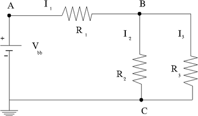
Construct the circuit below
Enter the values of the DC voltage and Resisters that you used.
Use a voltmeter to measure the potential difference and resistances.
| Variable | Measured Value |
Enter the measured and predicted quantities in the table below
Given and the values of all resistors, use Kirchoff's laws to predict
a.) Predict the value of
b.) Predict the values of the three currents.
c.) compare your predictions and measurements by filling in the table below.
| Variable | Measured Value | Predicted Value | % Difference |
| 1.414 V | 0.07 % | ||
| 1.57 mA | 1. 57 mA | 0.00 % | |
| 1.43 mA | 1.43 mA | 0.00 % | |
| 0.144 mA | 0.144 mA | 0.00 % |
Internal resistance (30 pnts)
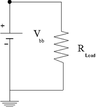
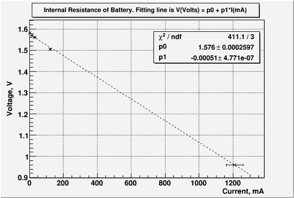
Measure the internal resistance of a "D" cell battery by graphing the current on the x-axis and the measured voltage on the y-axis for several values of the resistance shown in the circuit below. Begin with and then decrease it by a factor of 5 for each subsequent measurement. You can use a volt meter to measure the current and potential difference.
| R_{Load} () | V (Volts) | I (mA) |
| 990 | 1.536 | 1.56 |
| 99.4 | 1.529 | 15.20 |
| 46.3 | 1.519 | 31.82 |
| 10.3 | 1.448 | 121.8 |
| 0.47 | 0.667 | 1700 |
Questions (20 pnts)
- What conservation law is involved in Kirchoff's Loop Theorem?
- What does the slope in the internal resistance plot above represent?


