DDP:Detailed Design Phase: Drawing and Assembly Package
Detailed Design Drawing Report 6/27/08
Outline:
1.) Dimensions
2.) Constraints: Case 3 from progress report: constrain triangle and nose plate on upstream side.
3.) Deflection Analysis
Steps:
a.) check triangle contact region and its mass b.) add another carbon fiber rod c.) increase size of back plate
4.) Drawings
drawings in PDF format
a.) Endplate structural drawing (no holes just shaded area)
b.) Drawings for all other parts
c.)
d.) Copy old R3 (take advantage of no curved window.
Report
Introduction
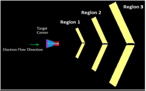
The CLAS12 Drift chamber has 3 regions arranged as shown below
The electrons released from the target center will flow through region 1, region 2 and region 3. All these regions look the same way. However, their sizes and the materials with which they are made are different. Due to the fact their sizes are different; some of them have some structural add-ons to support their structural abilities. The chambers are arranged in such a way that every chamber receives the same number of electrons. Apart from that, the chambers were shaped in such a way that all the electrons travel approximately the same distance before they hit a particular chamber.
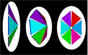
Each and every chamber has 6 equal sized pieces which are shaped similar to a triangular piece. All of these pieces are arranged and bowed inward to resemble sectors in a 6 sector umbrella.As discussed before, each region will be sized different. Region 3 will be the biggest of all, as region 3 has to cover a larger electron span (surface area).
Although these pieces are termed as triangular, these are not triangular in reality. The nose which is the smallest of all is very small compared to the other plates, which will make us to visualize this as a triangular piece. Ar Co2 (90/10) gas is maintained in each of these chambers at an operating pressure of 0.001444 Psi and a peak pressure 5 times higher. In turn there are about 4928 very sensitive wires (112 Sense wires with 44 Wire Layers) connected across the plates inside each piece.
Design Criteria
Initial parameters to be followed to fulfill to satisfy design Criteria
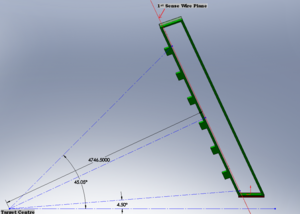
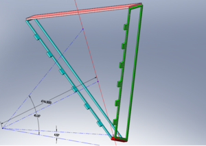
1. Distance from target to first sense wire plane along a ray which is normal to the end plate = 4746.5 mm
2. Chamber Tilt Angle = 25 Degrees
3. Maximum Scattering Angle = 45.05 Degrees
4. Minimum Scattering Angle = 4.5 Degrees
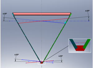
5. Wires are at 6 Degrees to the horizontal in each of its wire planes
Wire pattern
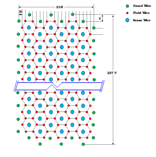
The wire pattern at the center plane will be symmetric and easy to understand. The wire pattern in each super layer on this plane is same and a view at this wires at this plane will be as follows
In the horizontal direction we have 6 six sense wires. so, there will be a 2 + 6 times 3 + 2 = 22 wire planes as shown in the fig. If the distance between each wire plane is 'H' mm. Then the total span of wires in this direction will be 21H mm.
In the vertical direction, there are 112 sense wires, so there will be 2 + 112 + 2 = 116 wire planes as shown. If the distance between each wire plane is 'V' mm. Then, the total span in this direction will be 115V mm
H = ?
V = ?
No. of sense wires in each super layer = ?
No. of field wires in each super layer = ?
No. of guard wires in each super layer = ?
Introduction to Assembly
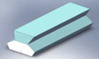
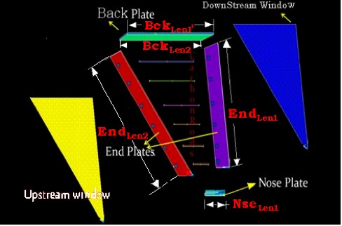
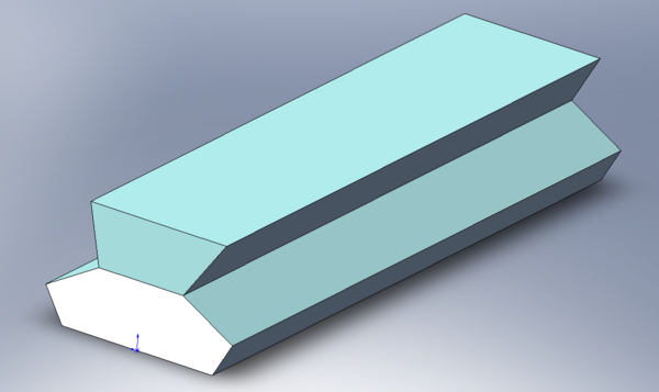
Nose Plate will be made of rigid material such as solid aluminum, since the supporting mechanism will be attached to these plates. The nose plate will connect the bottoms of the two end plated and provides the interface.
The End plate is about 4830 mm and 4665mm in length along the longitudinal length and about 525mm in width. It has approximately about 5000 holes with an approximate diameter of 6mm on the surface and about 9mm inside the surface. There will be two End plates names as Right End plate and Left End plate which are located to the actual right and left side of each sector when viewed from the target center respectively.
Back Plate: 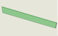 It is the plate which connects the top edges of both the end plates and holds the fixtures settings
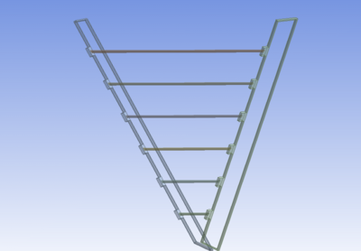
To provide rigidity, there will be several carbon rods fixed in between both the end plates and they vary in length depending on no.of carbon rods used and the location of rods. These rods are hollow to reduce the electron dissipation in the section.
Upstream Window and Downstream Window's:
Upstream Window is the thin Mylar sheet of about 1/1000th of an inch crimped or glued on the upstream side of electron flow slightly after the carbon rods. Downstream Window is a Hexcel honeycomb material provided on the downstream side to help support the assembly, to provide rigidity and to enclose each sector
Analysis
To determine the stability of the design, various sets of analysis were performed under different constraint and loading conditions. Sometimes each of the part was analyzed individually and also in the assembly. Some parts were analyzed for different materials
Part Analysis
End Plate
Drawings
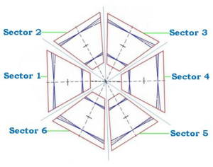
The Assembly of each sector in the region 3 drift chamber can be considered similar to each other. Each assembly can be divided into sub-assemblies like
1. Nose Plate
2. Right End Plate
3. Left End plate
4. Back plate
5. Backing Sheet
6. Carbon rods
7. Attachments: These are the external geometric parts of each sector, used for clamping and mounting each sector. so, they might change with the orientation of each sector
A detailed drawing of this Basic sector assmebly can be viewed at File:B00000-01-10-0001.pdf
Nose Plate
Nose plate is the plate where both the end plates are attached to it on either side
A detailed drawing of Nose plate can be viewed at File:B00000-01-10-0002.pdf
Right end plate
Left end plate is the end plate to the left hand side if we are viewing from the target.
They can be referenced with left and right to show each sub assembly.
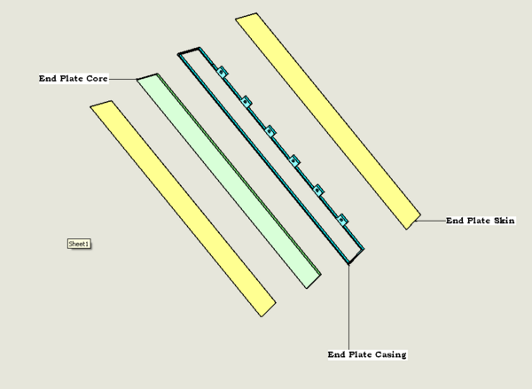
A detailed drawing of right end plate Core can be viewed at File:B00000-01-10-0003.pdf
A detailed drawing of right end plate skin can be viewed at File:B00000-01-10-0004.pdf
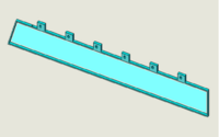
Since end plate casing will not have holes for wires, the drawing for left end plate casing and right end plate casing will be the same.
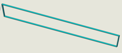
A detailed drawing of End plate casing can be viewed at File:B00000-01-10-0005.pdf
Left End Plate
Left end plate is the end plate to the left hand side if we are viewing from the target. Left end plate and the right end plate are same with parts and its dimensions. However, the hole locations differ between each other.
Each end plate sub assembly consists of 3 parts, namely
End plate casing - Made of Aluminum.
They can be referenced with left and right to show each sub assembly.
A detailed drawing of Left end plate Core can be viewed at File:B00000-01-10-0006.pdf
A detailed drawing of Left end plate skin can be viewed at File:B00000-01-10-0007.pdf
Back Plate
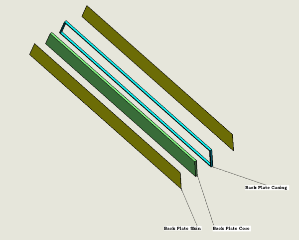
Back plate is the plate which connects the left end plate and right end plate on the top.
Back plate sub assembly consists of 3 parts, namely
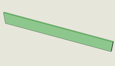
Back plate Core - made of Polyurethane
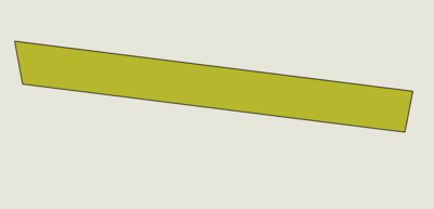
Back plate Skins - 2 No's- Made of stainless steel
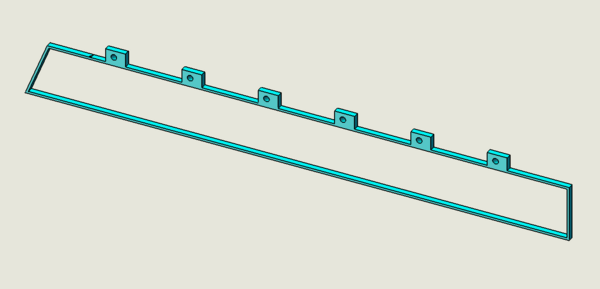
Back plate casing - Made of Aluminum
A detailed drawing of back plate Core can be viewed at File:B00000-01-10-0008.pdf
A detailed drawing of back plate skin can be viewed at File:B00000-01-10-0009.pdf
A detailed drawing of back plate casing can be viewed at File:B00000-01-10-0010.pdf
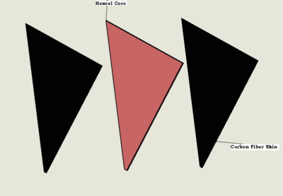
Backing Sheet
Backing sheet is the large sheet which is mounted on the downstream side of sector.
It consists of 2 parts, namely
Hexcel Core and Carbon fiber skins on either side
A detailed drawing of back plate Core can be viewed at File:B00000-01-10-0011.pdf
A detailed drawing of back plate skin can be viewed at File:B00000-01-10-0012.pdf
Carbon fiber rods
These rods are mounted on the upstream side of each sector, connecting the left end plate aluminum casing and right end plate aluminum casing..
There are 6 Carbon rods each of outer diameter of 50.8 mm and inner diameter of 48.26mm
A detailed drawing of carbon fiber rods can be viewed at File:B00000-01-10-0013.pdf
