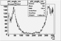
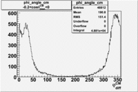
EC_total, [math]cos\theta_{pion}^{CM}[/math] vs [math]\phi_{diff}^{CM}[/math], missing mass, [math]\theta_{e}[/math] vs [math]\phi_{e}[/math]
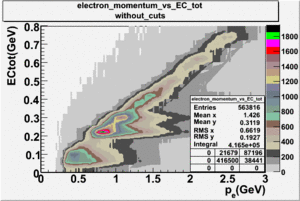
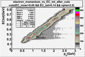
- Electron Momentum vs EC_total
- Missing Mass
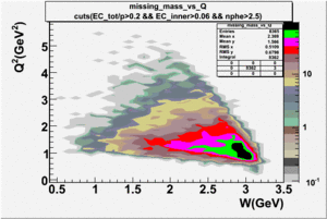
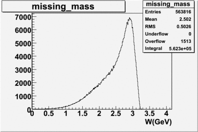
- [math]\theta_{e}^{LAB}[/math] vs [math]\phi_{e}^{LAB}[/math]
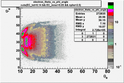
[1]
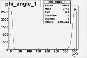
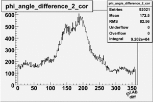
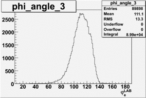
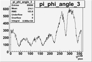
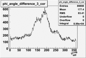
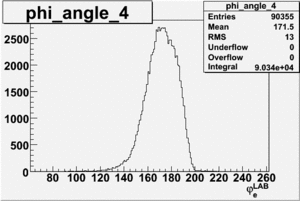
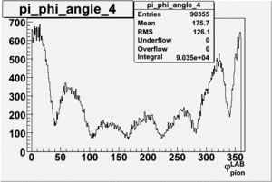
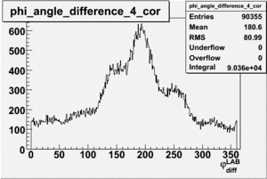
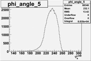
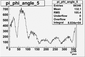
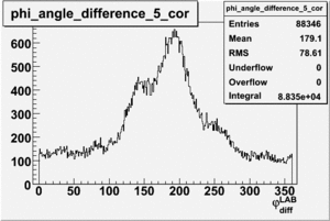
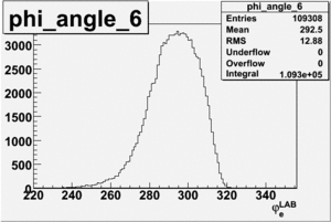
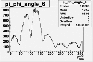
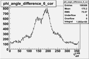
Phi lab [math]\varphi^{LAB}[/math]
The angle is (0, 360).
| electron sector |
[math]\varphi_{e}^{LAB}[/math] |
[math]\varphi_{pion}^{LAB}[/math] |
[math]\varphi_{e}^{LAB} - \varphi_{pion}^{LAB}[/math] after correction
|
| 1 |
 |
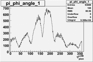 |
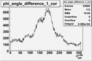
|
| 2 |
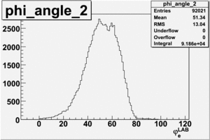 |
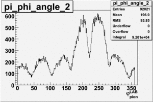 |
|
| 3 |
 |
 |
|
| 4 |
 |
 |
|
| 5 |
 |
 |
|
| 6 |
 |
 |
|
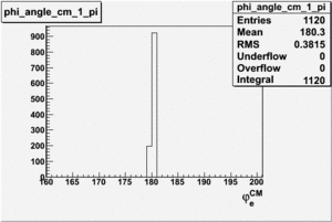
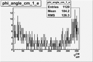
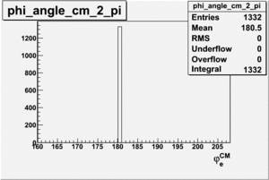
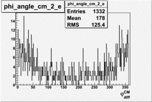
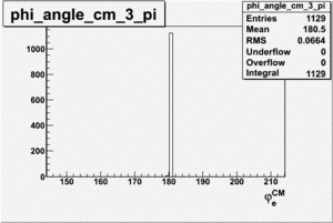
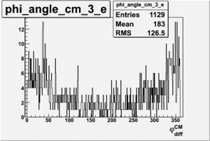
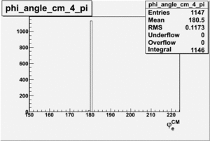
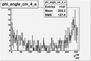
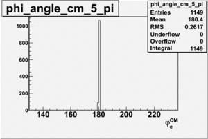
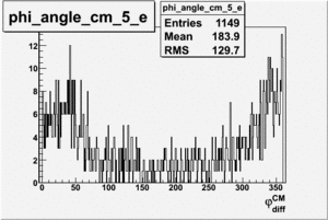
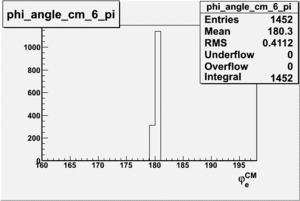
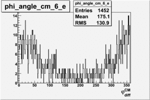
Phi CM [math]\varphi^{CM}[/math]
The phi angle after rotation and transformation to the CM frame
| electron sector |
[math]\varphi_{e}^{CM}[/math] |
[math]\varphi_{pion}^{CM}[/math]
|
| 1 |
 |
|
| 2 |
 |
|
| 3 |
 |
|
| 4 |
 |
|
| 5 |
 |
|
| 6 |
 |
|
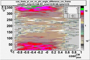
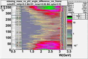
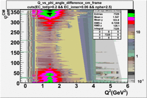
Correlation plots with[math]cos\theta_{pion}^{CM} , W[/math] , and [math] Q^2[/math]
The angle is (0, 360).
| [math]cos\theta_{pion}^{CM}[/math] vs [math]\phi_{diff}^{CM}[/math] |
[math]W[/math] vs [math]\phi_{diff}^{CM}[/math] |
[math]Q^2[/math] vs [math]\phi_{diff}^{CM}[/math]
|
 |
 |
|
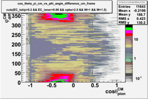
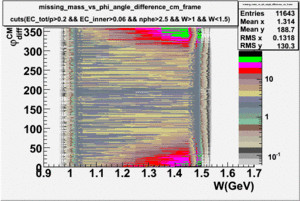
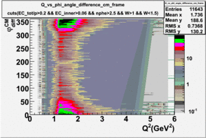
Same table as above but with the cut 1.0 < W < 1.5
| [math]cos\theta_{pion}^{CM}[/math] vs [math]\phi_{diff}^{CM}[/math] |
[math]W[/math] vs [math]\phi_{diff}^{CM}[/math] |
[math]Q^2[/math] vs [math]\phi_{diff}^{CM}[/math]
|
 |
 |
|
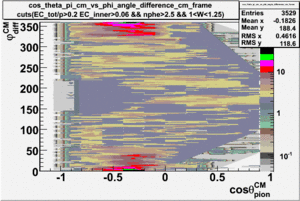
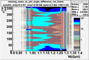
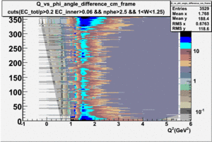
Same table as above but with the cuts 1.0 < W < 1.25 GeV , 20 MeV bins in W and 15 degree bins in [math]\phi[/math]
| [math]cos\theta_{pion}^{CM}[/math] vs [math]\phi_{diff}^{CM}[/math] |
[math]W[/math] vs [math]\phi_{diff}^{CM}[/math] |
[math]Q^2[/math] vs [math]\phi_{diff}^{CM}[/math]
|
 |
 |
|
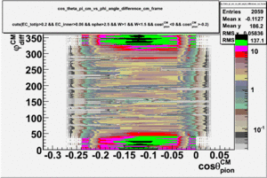
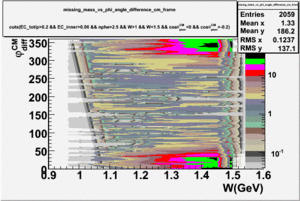
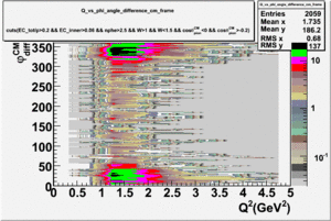
Same table as above but with the cuts 1.0 < W < 1.5 GeV and -0.2 < [math]cos\theta_{pion}^{CM}[/math] < 0
| [math]cos\theta_{pion}^{CM}[/math] vs [math]\phi_{diff}^{CM}[/math] |
[math]W[/math] vs [math]\phi_{diff}^{CM}[/math] |
[math]Q^2[/math] vs [math]\phi_{diff}^{CM}[/math]
|
 |
 |
|
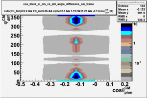
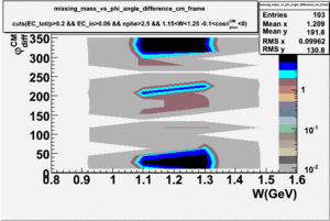
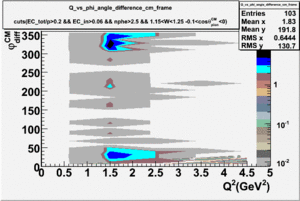
Insert the same table as above but with the cuts 1.15 < W < 1.25 GeV and -0.1 < [math]cos\theta_{pion}^{CM}[/math] < 0, 20 MeV bins in W and 15 degree bins in [math]\phi[/math]
| [math]cos\theta_{pion}^{CM}[/math] vs [math]\phi_{diff}^{CM}[/math] |
[math]W[/math] vs [math]\phi_{diff}^{CM}[/math] |
[math]Q^2[/math] vs [math]\phi_{diff}^{CM}[/math]
|
 |
 |
|
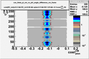
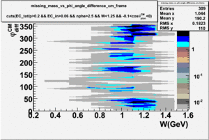
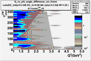
Insert the same table as above but with the cuts W < 1.25 GeV and -0.1 < [math]cos\theta_{pion}^{CM}[/math] < 0, 20 MeV bins in W and 15 degree bins in [math]\phi[/math]
| [math]cos\theta_{pion}^{CM}[/math] vs [math]\phi_{diff}^{CM}[/math] |
[math]W[/math] vs [math]\phi_{diff}^{CM}[/math] |
[math]Q^2[/math] vs [math]\phi_{diff}^{CM}[/math]
|
 |
 |
|
[2]
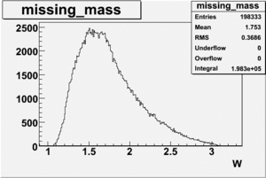
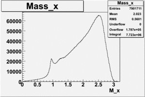
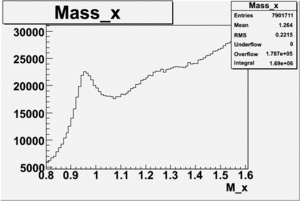
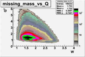
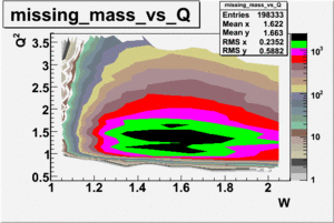
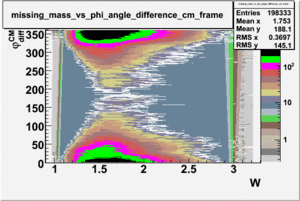
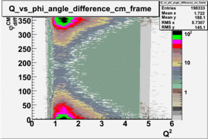
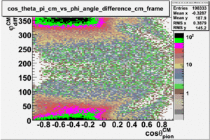
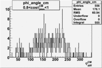
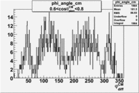
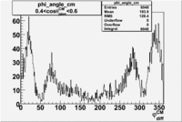
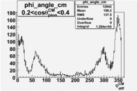
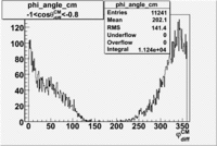
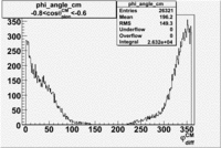
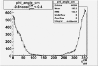
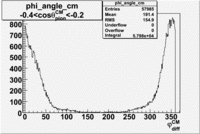
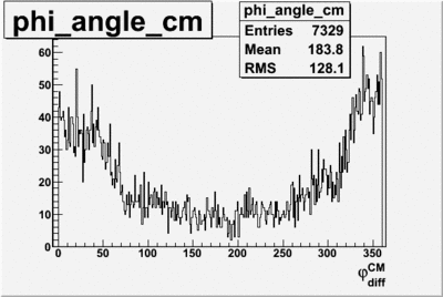
Phi_angle_in_CM_Frame for different [math]cos\theta_{pion}^{CM}[/math] cuts
Used 1735 files. The following cuts are applied: [math]0.9\lt M_x\lt 1.1[/math], [math]1.1\lt W\lt 1.5[/math] and EC cuts.
Insert plot of M_x and W to show cuts
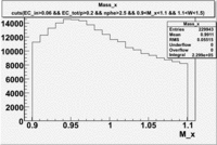
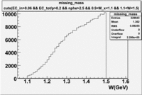
Then insert phi -vs- theta
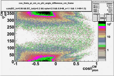
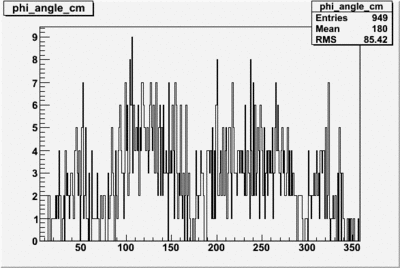
Cuts: EC_inner>0.06, EC_tot/p>0.2, nphe>2.5, [math]0.9\lt M_x\lt 1.1[/math], [math]1.1\lt W\lt 1.5[/math] and [math]0.6\lt cos\theta_{pion}^{CM}\lt 0.8[/math].
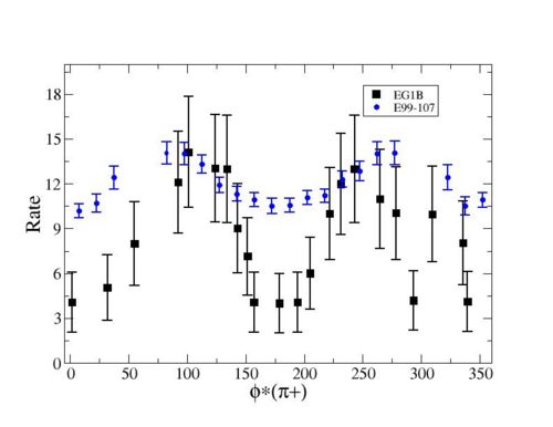
 1.4 < Q^2 < 1.8   1.13< W <1.17
not a good one
[Back to Analysis]


