IAC positron beamline
Sketched (not to scale) layout of the 25 MeV beamline:
296 cm = parrallel Distance From the end of the accelerator module (After RF cavities) to experimental cell port
280 cm = Distance From accelerator zero degree beamline to Experimental Cell Wall
56 cm = distance between flanges for the first dipole
84 cm = distance between flanges for the first quad doublet
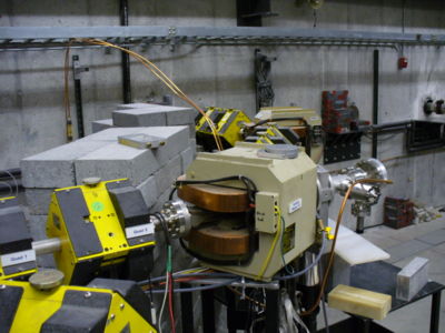
This picture shows you the current 90 degree bend into the experimental hall. Quad 1 and Quad 2 are shown and then the 2nd Dipole magnet (labeled Bending Magnet 2A a.k.a. Dipole 2) begins after Quad 1 and Quad 2. Dipole 2 is following by another Quad doublet and then a Dipole (Dipole 3) and then a final quad doublet before going through the wall into the experimental cell.
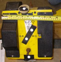
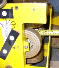
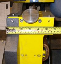
Length of Iron =
Diameter of Coils=
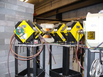
The next picture was taken upstream of the 90 degree bend and shows Dipole 1 which is usually off unless we want to bend beam right into the accelerator hall instead of going straight to Quad 1 and Quad 2.
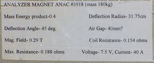
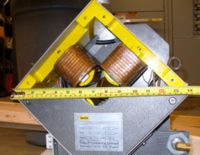
Label on side of Dipole 1
Label on side of Dipole 2
The Quad doublets in the current beam line have the following label.
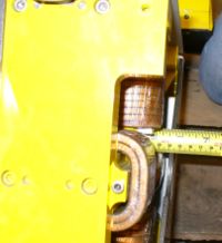
Quad doublet size:
We also have Quad triplet which take up less space than the doubles.
