DC Binning Based On Wire Numbers
Jump to navigation
Jump to search
![Layer1bins.png](/./images/f/f1/Layer1bins.png)
![Layer1bins Isotropic.png](/./images/a/ae/Layer1bins_Isotropic.png)
![Layer1binWeighted.png](/./images/8/8b/Layer1binWeighted.png)
![MolThetaLabWeighted.png](/./images/8/84/MolThetaLabWeighted.png)
![Layer1binWeighted Isotropic.png](/./images/c/ca/Layer1binWeighted_Isotropic.png)
![MolThetaLabWeighted2.png](/./images/0/06/MolThetaLabWeighted2.png)
![MolThetaWireWeighted.png](/./images/c/cd/MolThetaWireWeighted.png)
![MolThetaWireWeightedIsotropic.png](/./images/9/94/MolThetaWireWeightedIsotropic.png)
![MolThetaWireWeightedAdjusted.png](/./images/7/72/MolThetaWireWeightedAdjusted.png)
![MolThetaWireWeightedAdjustedIsotropic.png](/./images/9/9c/MolThetaWireWeightedAdjustedIsotropic.png)
![TheoryDCbinsWire.png](/./images/a/aa/TheoryDCbinsWire.png)
![TheoryDCbinsWireIsotropic.png](/./images/0/08/TheoryDCbinsWireIsotropic.png)
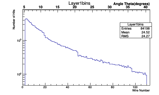
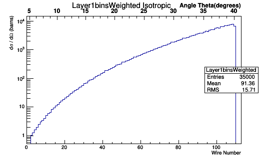
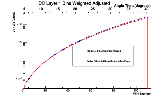
The bin size based on wire number will need to be a uniform width of 1, as in an increment of 1 between the integer values of the wires. This uniformity in bin size based on wire numbers is not uniform when viewed by the angle theta due to the Drift Chamber geometry discussed earlier.
Modifying evioreader
![Layer1bins.png](/./images/f/f1/Layer1bins.png)
![Layer1bins Isotropic.png](/./images/a/ae/Layer1bins_Isotropic.png)
gStyle->SetStripDecimals(kTRUE); TF1 *fit_function=new TF1("fit_function","[0]+[1]*x+[2]*x*x+[3]*x*x*x",4.49876,41.12592); fit_function->SetParameters(4.49876,0.293001,0.000679074,-0.00000357132); TGaxis *A1 = new TGaxis(0,5000,113,5000,"fit_function",510,"-"); A1->SetTitle("Angle Theta(degrees)"); A1->Draw();
![Layer1binWeighted.png](/./images/8/8b/Layer1binWeighted.png)
![MolThetaLabWeighted.png](/./images/8/84/MolThetaLabWeighted.png)
![Layer1binWeighted Isotropic.png](/./images/c/ca/Layer1binWeighted_Isotropic.png)
![MolThetaLabWeighted2.png](/./images/0/06/MolThetaLabWeighted2.png)
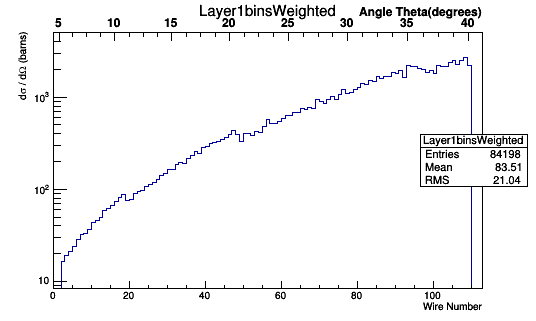
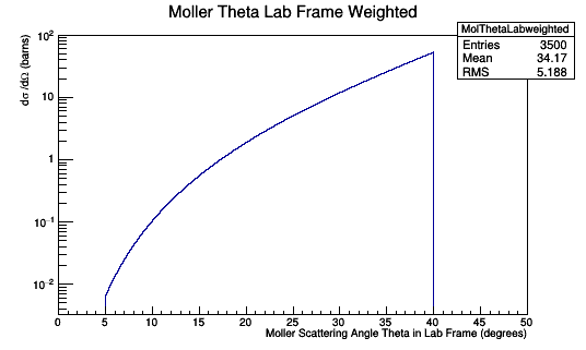
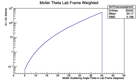
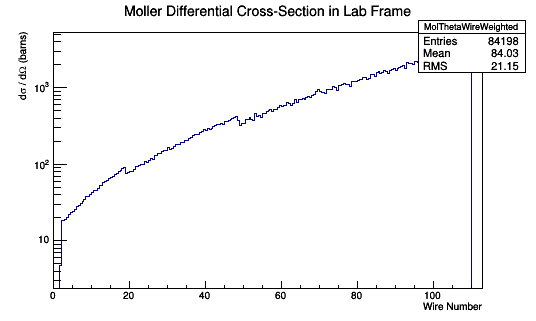
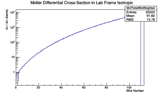
Using the expression for n in terms of Theta:
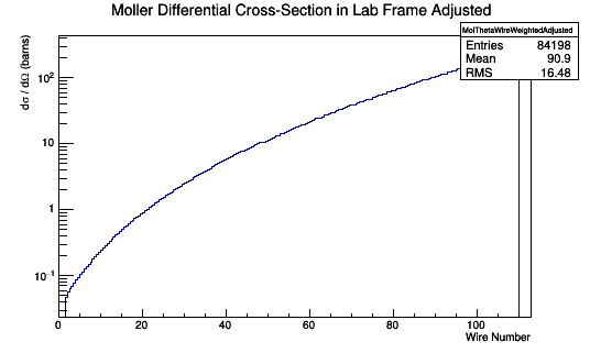
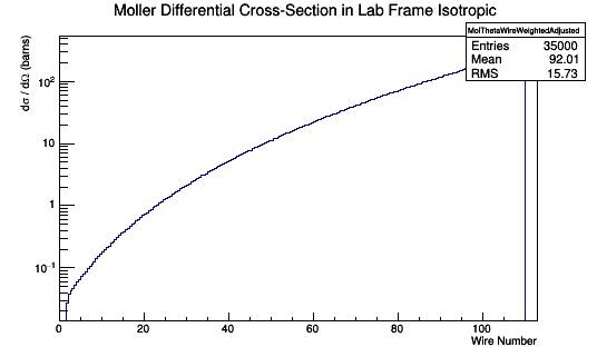
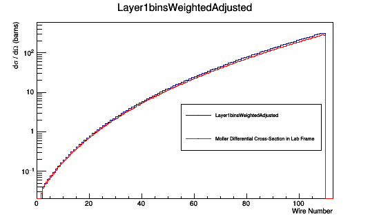
This relationship can be used to multiply each Moller Scattering angle theta in the lab frame, with it's differential cross-section weight, to find the Moller differential cross-section as a function of wire number in the lab frame.
![MolThetaWireWeighted.png](/./images/c/cd/MolThetaWireWeighted.png)
![MolThetaWireWeightedIsotropic.png](/./images/9/94/MolThetaWireWeightedIsotropic.png)
![MolThetaWireWeightedAdjusted.png](/./images/7/72/MolThetaWireWeightedAdjusted.png)
![MolThetaWireWeightedAdjustedIsotropic.png](/./images/9/9c/MolThetaWireWeightedAdjustedIsotropic.png)
![TheoryDCbinsWire.png](/./images/a/aa/TheoryDCbinsWire.png)
![TheoryDCbinsWireIsotropic.png](/./images/0/08/TheoryDCbinsWireIsotropic.png)