05-3-2017
Electronics map for the two auxiliary scintillators
| Phi Angle (Degrees) | PMT distance | Signal cable label | HV cable label | HV channel on Lecroy Mainframe | CFD CH | VNIM-ECL channel | ROOT variable |
|---|---|---|---|---|---|---|---|
| ~282 | m | 102B1.2 | shv1.2 | 5:L1.2 | 1 | (left) B-0 | evt.TDC[1][25] |
| ~282 | m | 282T1.7 | shv1.7 | 5:L1.7 | 2 | (left) B-1 | evt.TDC[1][26] |
run list
He-3 timing is in patch panel 223A16, & energy is 223A17.
High voltage & discriminator settings:
30T: 1450;30 , 30B:1450;30 , 54T: 1500;30 , 54B: 1500;30 , 78T:1500;30 , 78B: 1525;30 , 126T: 1500;30 , 126B: 1500;30 , 150T: 1500;40 , 150B: 1500;40 , 210T: 1500;40 , 210B: 1500;40 , 234T: 1500;30 , 234B: 1500;30 , 258T: 1350;30, 258B: 1450;30 , 306T: 1400;30 , 306B: 1400;30 , 330T: 1450;30 , 330B: 1500;30
Radiator 1.5" Al.
Slits currently at 500 => 19 mm, at 75 =0, at 1000=38 mm, readback number is linear with slit width.
Small aux. scintillators have a CFD threshold of 0.550 V for run 6274 and later.
| Run # | Charge/pulse | Target | Configuration | Individual histos + rates | overlayed histos | All PMT's no coinc. |
|---|---|---|---|---|---|---|
| 6286 | Integral=12.5 pV*s 1.5 mV peak = 1.4A | Empty | 10.6 MeV (1123 Gauss) , 3 ns FWHM pulse width , 1.4 A Peak , 180.4 Hz , Removed small Scint at .725 m Kept Scint in at 1.45 m, |
beam profile
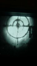
circle=2cm ; inner ring = 5cm ; outter ring = 10 cm
