Detector Description
The detectors are very sensitive devices, its components are connected to high voltage power supplies in a relatively thin chamber with Ar/CO2 90/10 gas mixture. As a result, the method of construction demands a laminar flow hood that accommodate a clean environment from any source of dust in the atmosphere or any surrounding objects, Also the gloves are used to avoid any particle transfer to the detector's parts or components through the steps of its construction.
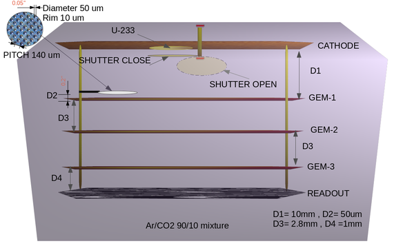
The GEM based neutron detector consists of :
1- A cathode; a square copper plate has a dimension of 10x10cm and has a distance of 1.6 cm from the top of the fist GEM card. The cathode design allows to raise the potential on its surface up to 5 kV (in air) without any discharge effect.
2- A neutron sensitive material; in our case U-233 have been used as a sensitive material and has relatively a high fission cross in the desired energy range, U-233 is coated on the top of a metal plate in circular disk that has a diameter of 3cm and fixed as a part of the detector cathode's surface.
3- GEM cards; the detector has three GEM cards in square plastic frames, they have dimension of 10x10cm and are placed parallel to the cathode as shown in the figure below.
Each GEM preamplifier card is made of a copper clad kipton plate of a thickness 50 um and an area of 10x10cm, It has Holes with a diameter of 50 um which are chemically etched in an equilateral triangular pattern with 70 um pitch distance.
4- A chamber, All the previous components exist in a plastic chamber, it has been sealed to insulate the chamber's gas has from the atmospheric gas components.
The chamber has a square window of kipton of dimension of 13x13cm.
The detector operates by providing the high voltage circuit by two channel high voltage power supply up to 3.1 kV for the cathode, and up to 2.8 kV for the GEM cards.
The circuit diagram is shown in the figure below:
The circuit will provide a potential difference between the top and the bottom of each card in the range of 300-350 V.

