TF EIM Chapt5
Half Wave rectifier
A half wave rectifier is a circuit which passes only half of the input AC waveform.
This is accomplished by using the diode's forward drop voltage to "clip" the AC signal.
Consider the following circuit
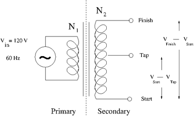
The Transformer
A transformer uses inductors/coils to step voltages either up or down based on the ratio of the number of coil turns and .
Let represent the magnetic flux seen by the inductors due to the changing current in the primary.
- = Input Voltage on the Primary side
- = Output Voltage on the Secondary
The ground is relative for a transfer. You could use the "Tap" or center post as a ground and either the Start or Finish end
- = Output voltage between Tap and Secondary
Where ground
Since both coils see the same flux
If you have a step UP (Voltage increasing) Transformer
If you have a step DOWN (Voltage decreasing) Transformer
