Lab 9 RS
Lab 9: Diode Circuits
Clipping Circuit
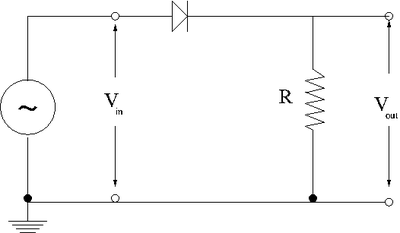
1.) Construct the circuit shown below using a silicon diode.
2.) Use a sine wave generator to drive the circuit so where V and = 1kHz. (20 pnts)
3.) Based on your observations using a oscilloscope, sketch the voltages and as a function of time.
4.) Do another sketch for = 1.0 V and another for 10.0 V (DONT LET ANY SMOKE OUT!). (20 pnts)
Roman
++Roman++
Roman
Roman
Roman
Roman
Differentiating Circuit with clipping
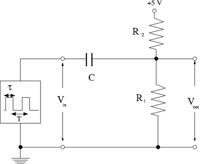
1) Construct the circuit below.
2) Select and such that the current from the +5V DC source is less than 1.0 mA and the DC voltage at is 3 V when there is no input pulse.
Because we want to keep the current below and using . Solving this inequality we get the first condition for and
Also because we want and using . Without any input pulse . Solving this simple equation we get the second condition for and
I am going to use and which satisfy both conditions above
3) Select a capacitor and a pulse width to form a differentiating circuit for the pulse from the signal generator. Hint: .
Taking and .
And choosing the the pulse width I will be able to make a good differentiator circuit.
4) plot and as a function of time using your scope observations. (20 pnts)
5) Now add the diode circuit from part 1 to prevent from rising above +5 V. Sketch the new circuit below.
6) plot and as a function of time with the diode circuit you added using your scope observations. (the diode should clip off positive spikes) (20 pnts)
Questions
- Explain your results in parts 1 & 2 in terms of the diode turn-on voltage. (20 pnts)
Forest_Electronic_Instrumentation_and_Measurement Go Back to All Lab Reports

