Lab 8 TF EIM
Lab 8 The Diode Objective: Measure the current-voltage curve of a silicon diode.
Reverse current
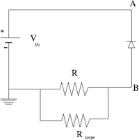
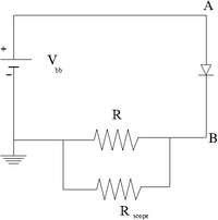
1.) Construct the circuit below using a DC power supply, a diode.
2.) Attach an Oscilloscope with internal resistance . The scope will measure the voltage drop across R and thus the current will be given by this voltage difference divided by R.
3.) Determine a value for R which will allow you to measure a current of at least 10 mA (prefeferably 50 mA) at the diodes reverse bias cut off voltage. Show your power calculation. (5 pnts)
4.) Measure the diode reverse current as a function of the DC supply voltage. (20 pnts)
| Bias Voltage | V_{scope} | Current (V/R) | Diode power | R power |
5.) Fill in the blank. The reverse biased diode act as a constant _______________ source. (5 pnts)
Forward Current
1.) now swap the diode direction and repeat the measurement in the previous section.
2.) Attach an Oscilloscope with internal resistance . The scope will measure the voltage drop across R and thus the current will be given by this voltage difference divided by R.
3.) Determine a value for R which will allow you to measure a current of at least 10 mA (prefeferably 50 mA) at the diodes reverse bias cut off voltage.
4.) Measure the diode forward current as a function of the DC supply voltage. (25 pnts)
| Bias Voltage | V_{scope} | Current (V/R) | Diode power | R power |
5.) Fill in the blank. The forward biased diode act as a constant _______________ source. (5 pnts)
Graph
- Plot the diode current (on the ordinate) versus the diode voltage (on the abscissa)for the forward and reverse biased diode on the same graph. (20 pnts)
Questions
1.) Plot the reverse biased diode for voltages beyond the turn on voltage in order to measure the effective impedance of the diode assuming a linear fit.
2.)The measured reverse biased turn on voltage is _________ Volts for silicon diode IN_____________. The % difference between the measured turn on voltage and the one given in the specification is __________%. This % difference is/is not within the measurement uncertainty.
3.) Plot the forward biased diode in order to measure the effective impedance of the diode assuming a linear fit.

