TF EIM Chapt2
Alternating Current (AC)
Thus far we have discussed direct current circuits which were built from a battery (constant voltage supply).
Another type of circuit is one in which the current is driven in an alternating fashion. Typically the current is increased so some positive maximum value, then decreased until it passes through zero and reverses direction until it reaches another maximum value and then it is decreased again, passing though zero once more on its way to a positive maximum value.
Definitions
- frequency (, )
- The frequency is number of complete cycles which occur in 1 sec (cycles/sec = Hz)
- Angular frequency = = radians/sec
- Period
- The period is the time to complete one cycle = 1/
- Amplitude
- The change in the current from zero to its most positive value
- peak-to-peak
- The amount the current changes from its largest positive value to its most negative.
- phase
- The time a current takes to reaches its maximum value compared to another alternating current
- Note
- The above definitions can be used for voltage as easily as current.
Mathematical description
Trigonometric
- Note
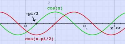
- A 180 degree ( radian) phase shift will put the above cosine wave completely out of sync with the original one such that if we add the two signals together the net current would be zero.
I_{RMS}
With this functional form for the alternating current we can now calculate another property, the RMS or root mean square.
The RMS quantifies an average fluctuation of the alternating current such that
where T represent the time interval over which the average is calculated ()
- if T is infinite or an integer number of cycles
Power
The instantaneous power dissipated in a resister by an alternating current is given as
Average power
Plane waves
Another mathematical expression for an alternating current uses complex variables
Expressing the current in this form will be useful later
Voltage sources of AC current
The circuit symbol for an emf used to drive alternating currents is given below
The mathematical form is
Capacitors
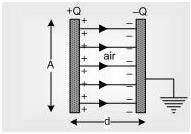
A capacitor is a device used to store charge in a circuit. The simplest capacitor is built from two conducting plates placed close to each other.
- Noteice
- The potential is constant over the face of the capacitor
The symbol for a capacitor in a circuit reflects this.
dielectric
dielectric capacitors can be shorted out. Put the positive probe from the voltmeter on the positive side of the electrolytic capacitor, the capacitor should be good if you measure a large resistance otherwise a shorted electrolytic capacitor (small resistance) is a bad one.
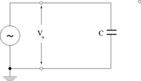
Capacitor circuit
If
then applying loop theorem lead to
- Notice that the current is 90 degrees out of phase with the driving voltage.
- Note
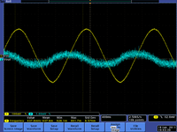
- The current increases faster than the voltage. Below are a few scope pictures measuring the voltage coming out of the voltage source and the voltage on the ground side of the capacitor (the capacitor is grounded through the scope).
| 1 Hz | 10kHz | MHz |
File:TF EIM CapChargeScopePic kHz.png kHz frequency |
File:TF EIM CapChargeScopePic MHz.png MHz frequency |
Resistive nature of capacitance
To illustrate the resistive nature of capacitors, let's write the driving voltage in using complex notation
The notation
- : Euler's equation
- The real part of a complex variable.
The current is written as
where
- Effective impedance of a Capacitor
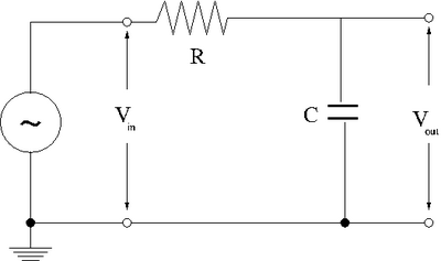
RC circuit
Now add a resistor in series with the capacitor in the above capacitor charging circuit.
Again apply the loop theorem
or
- First order linear differential equation
