DDP:Detailed Design Phase: Drawing and Assembly Package
Detailed Design Drawing Report 6/27/08
Outline:
1.) Dimensions
2.) Constraints: Case 3 from progress report: constrain triangle and nose plate on upstream side.
3.) Deflection Analysis
Steps:
a.) check triangle contact region and its mass b.) add another carbon fiber rod c.) increase size of back plate
4.) Drawings
drawings in PDF format
a.) Endplate structural drawing (no holes just shaded area)
b.) Drawings for all other parts
c.) drawing showing how parts are bolted together
d.) Copy old R3 (take advantage of no curved window.
Report
Basic understanding
This section of the report will deal with the basic understanding of the region 3 in the nuclear Drift Chamber. This is where the required geometric parameters are understood.
Initial parameters to be followed to fulfill to satisfy design Criteria
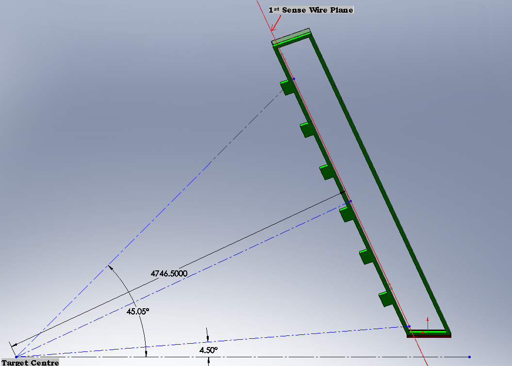
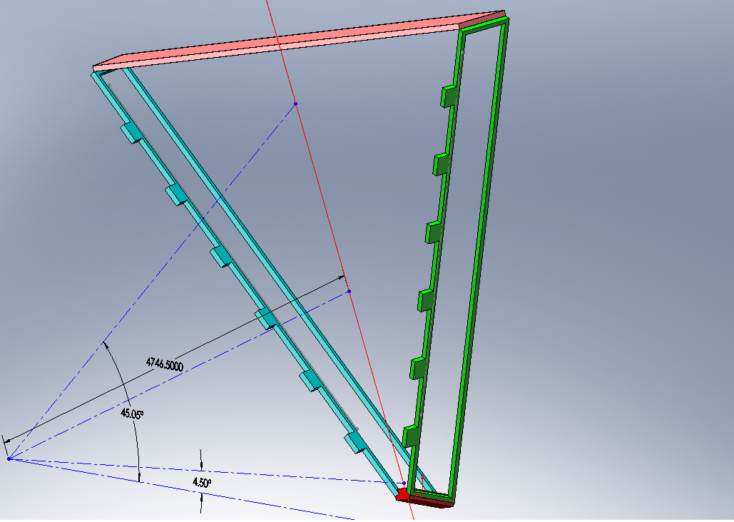
1. Distance from target to first sense wire plane along a ray which is normal to the end plate = 4746.5 mm
2. Chamber Tilt Angle = 25 Degrees
3. Maximum Scattering Angle = 45.05 Degrees
4. Minimum Scattering Angle = 4.5 Degrees
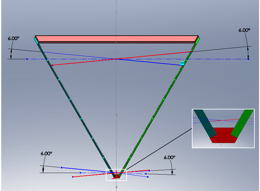
5. Wires are at 6 Degrees to the horizontal in each of its wire planes


