R3DC Report 2-08
Introduction
R3 Description
Geometry
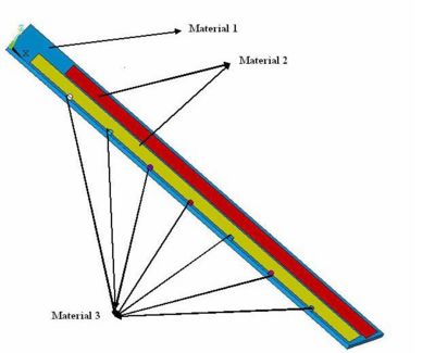
Material Specifications
| Material | Youngs Modulus | Density |
| MPa | ||
| Polyeurethane Foam FR-3700 | 140 | 240 |
| Hexacell with holes | ||
| Carbon Fiber Rods | 210 | 580 |
Specific part Drawings
Endplate Deflection
Point Load Deflection
A simple calculation based on the definition of Young's modulus can yield an order of magnitude level estimate for the deflection of an endplate made from Aluminum. According to the definition of Young's modulus
where
- Young's Modulus for Aluminum
- point force/load
- width of the endplate
- deflection of endplate due to point force
- length of the endplate
- thickness of the endplate
A deflection of 6 mm is expected for a 5 cm thick Aluminum endplate, after solving the above equation for and inserting the given values. If a 5 cm thick stainless steel endplate were used, the deflection would drop a factor of 3 from 6 mm to 2 mm due to the linear dependence of the deflection on Young's Modulus. The previous work of Kevin Folkman led to a similar conclusion.
Distributed Load Deflection
The endplate deflection calculation redone assuming a distributed load instead of a point load in order to determine how much the distribution of the load would help reduce the endplate deflection. The existence of holes in the endplate were also considered by defining three different distributed loads based on the geometry of the holes in the endplate. As shown in the Figure below, the load W3 corresponds to a region along the endplate in which the endplate holes for both drift chamber super layers are present. Loads W2 and W1 are loads in which the number of endplate holes differ. The endplate is "simply" supported in order to calculate the deflection. The "simple" support has a point support on the left side in which the endplate may rotate but not translate (move left or right). The right hand side of the plate is support such that the endplate can both rotate and translate.
Distributed load FEA
In addition to validating the FEA analysis with hand calculations, the above results also reveal the challenge of reducing the endplate deflection using stiffer Materials due to an essentially linear dependence of the deflection to Young's Modulus. The cubic dependence of the deflection on the thickness of the endplate, however, can be used to reach the minimum endplate deflection criteria of 50 instead of using stiffer material. Increasing the endplate thickness comes at the cost of increasing the end plate mass. As a result, composite materials were considered in order to minimize weight.
Carbon Rod Buckling
Compression
Buckling Load Threshold
Buckling FEA
=3-D Analysis
